Working table with guide rail

A technology of workbench and guide rail, which is applied in the direction of manufacturing tools, metal processing equipment, metal processing machinery parts, etc., can solve the problems of large wear, affecting the machining accuracy of machine tools, and inconvenience

Inactive Publication Date: 2015-03-25
常州矩阵精密机械有限公司
View PDF0 Cites 5 Cited by
  • Summary
  • Abstract
  • Description
  • Claims
  • Application Information

AI Technical Summary

Problems solved by technology

[0002] When the machine tool is running, there is a certain amount of wear between the machine tool table and the guide rail. After a long period of use, the wear between the machine tool table and the guide rail is relatively large, which causes the machine tool table to "crawl" when the guid

Method used


Image

  • Working table with guide rail

Examples


Embodiment Construction

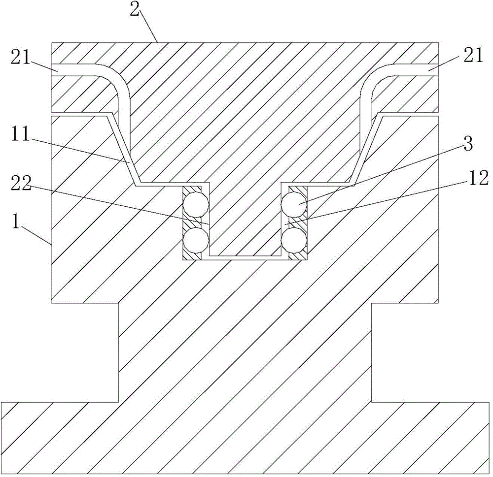
[0010] The present invention will be further described below in conjunction with the accompanying drawings and specific embodiments.

[0011] Such as figure 1 , a workbench with a guide rail, including a guide rail 1 and a workbench 2, the upper end of the guide rail 1 is provided with a U-shaped groove 11, and a sliding groove 12 is arranged in the U-shaped groove 11, and balls 3 are arranged on both sides of the sliding groove 12 , the workbench 2 is set as a T-shaped structure adapted to the guide rail 1, and the bottom end of the workbench 2 is provided with a guide block 22 adapted to the slide groove 12, and the guide block 22 is in contact with the ball 3 in the slide groove 12 and Through rolling and sliding of the ball 3 , oil grooves 21 are provided on both sides of the workbench 2 , and the oil grooves 21 communicate with the side surfaces of the U-shaped groove 11 .

[0012] The sliding groove 12 is provided with a mounting groove for mounting the ball 3 .

[001...


PUM


Abstract

The invention relates to a working table with a guide rail. The working table comprises the guide rail and a working table body, a U-type groove is formed in the upper end face of the guide rail and internally provided with a sliding groove, roll balls are arranged on the two sides of the sliding groove, the working table body is arranged to be of a T-type structure matched with the guide rail, a guide block matched with the sliding groove is arranged at the bottom end of the working table body, makes contact with the roll balls in the sliding groove and slides through rolling of the roll balls, and oil ducts are formed in the two side faces of the working table body and communicated with the side faces of the U-type groove. The working table has the advantages of being simple in structure and convenient to lubricate and will not deflect in the sliding process, and friction loss between the working table body and the guide rail is reduced.

Description

technical field [0001] The invention relates to the technical field of machine tool components, in particular to a workbench with guide rails. Background technique [0002] When the machine tool is running, there is a certain amount of wear between the machine tool table and the guide rail. After a long period of use, the wear between the machine tool table and the guide rail is relatively large, which causes the machine tool table to "crawl" when the guide rail moves. , affecting the machining accuracy of the machine tool. In order to reduce the wear between the machine table and the guide rail, the method of adding lubricating oil is usually used, that is, manually brushing the guide rail with a brush dipped in oil, which is extremely inconvenient. Contents of the invention [0003] In view of the above problems, the object of the present invention is to provide a workbench with guide rails which has a simple structure, no deviation during the sliding process of the wor...

Claims


Application Information

Patent Timeline
IPC IPC(8): B23Q1/01B23Q1/25B23Q11/12
CPCB23Q1/017B23Q1/25B23Q11/124
Inventor 胡晨
Owner 常州矩阵精密机械有限公司
Why Eureka
Try Eureka