
Structural steel surface sanding device

A technology of sand grinding and section steel, which is applied in the direction of grinding/polishing equipment, metal processing equipment, and machine tools designed for grinding the rotating surface of workpieces. Quality damage and other problems, to achieve good protection effect, improve sanding efficiency, and not easy to damage

Active Publication Date: 2015-03-25
宝武特冶航研科技有限公司
View PDF8 Cites 5 Cited by
  • Summary
  • Abstract
  • Description
  • Claims
  • Application Information

AI Technical Summary

Problems solved by technology

[0004] The existing sanding equipment for the surface of section steel usually controls the grinding wheel by manually manipulating the cantilever, which has the disadvantage of inconvenient operation. At the same time, when the grinding wheel is in contact with the section steel, the impact energy is often generated due to excessive pressing force. The rigid and fast movement of the grinding wheel head on the round steel is likely to cause damage to the surface quality of the steel, and at the same time have a great impact on the operation safety of the grinding machine and the strength of the grinding wheel. Operator's life safety
In addition, in the existing steel surface sanding equipment, the grinding wheel motor is generally fixed on the cantilever by the mounting seat, so that when the belt is replaced for maintenance, there is a defect that the belt is inconvenient to replace

Method used


Image

  • Structural steel surface sanding device

Examples


Embodiment Construction

[0026] The present invention will be further described in detail below in combination with specific embodiments.

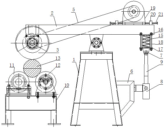
[0027] During specific implementation: if figure 1 As shown, a type of steel surface sanding equipment includes a frame 1, a grinder arranged on the frame 1 and a material holding device arranged on one side of the frame 1. The grinder includes a rotatable device connected to the frame 1 The cantilever 2 at the upper end and the grinding wheel sheet 3 and the grinding wheel motor 4 respectively located at both ends of the cantilever 2, the grinding wheel sheet 3 is located above the material holding device, and the output end of the grinding wheel motor 4 is connected to the grinding wheel sheet 3 through a belt 5 and used to drive the grinding wheel sheet 3 to rotate; Wherein, the lower part of the frame 1 is further provided with a cylinder mount 6 on the side away from the material holding device, and a cylinder 8 is hingedly arranged on the cylinder mount 6. ...


PUM


Abstract

The invention discloses a structural steel surface sanding device. The device comprises a machine frame, a grinding machine arranged on the machine frame, and a containing device arranged on one side of the machine frame, wherein the grinding machine comprises a cantilever arranged at the upper end of the machine frame in a rotary mode, a grinding wheel disc and a grinding wheel motor, the grinding wheel disc and the grinding wheel motor are located at the two ends of the cantilever respectively, the grinding wheel disc is located above the containing device, and the output end of the grinding wheel motor is connected with the grinding wheel disc through a belt and is used for driving the grinding wheel disc to rotate. The device is characterized in that a cylinder installation base is further arranged on the side, away from the containing device, of the lower portion of the machine frame, a cylinder is hinged to the cylinder installation base, and a telescopic arm of the cylinder is arranged upwards and is connected with the end, provided with the grinding wheel motor, of the cantilever. The device has the advantages that the structure is simple, operation and control are easy, sanding efficiency is high, the surface of round steel is not damaged easily, grinding wheel protecting effect is good, and safety performance is higher.

Description

technical field [0001] The invention relates to a type steel surface treatment technology, in particular to a type steel surface sand grinding equipment. Background technique [0002] Section steel refers to long steel with a certain cross-sectional shape, such as square steel, I-beam, angle steel, etc. In the production process of section steel of some special materials, it is necessary to sand the surface of the billet. Especially the outer circle sanding of round steel is an indispensable process. Sanding treatment is mainly to eliminate the rust or oxide layer on the surface of the billet to check the surface quality of the material, so as to find defects and carry out process treatment in a timely manner. Make a reliable guarantee for the quality of the next process. [0003] In order to improve efficiency, the existing steel surface sanding equipment generally includes a frame, a grinder arranged on the frame and a material holding device arranged on one side of the...

Claims


Application Information

Patent Timeline
IPC IPC(8): B24B27/033
CPCB24B5/22B24B5/307B24B27/0076B24B27/04B24B41/007
Inventor 董宝渝
Owner 宝武特冶航研科技有限公司
Learn More