
Optic nerve implantable neural interface device with fan-shaped attaching function

An interface device and optic nerve technology, which is applied in the field of biomedical engineering, can solve the problems that the stimulation electrode array is not easy to fix, the optic nerve space is extremely narrow, the optic nerve is easy to slide, etc., and achieves low surgical risk, good flexibility, and good biocompatibility. Effect

Active Publication Date: 2012-11-28
SHANGHAI JIAO TONG UNIV
View PDF13 Cites 10 Cited by
  • Summary
  • Abstract
  • Description
  • Claims
  • Application Information

AI Technical Summary

Problems solved by technology

Due to the special anatomical structure of the optic nerve, the implantation of the stimulating electrode array has the following technical difficulties: (1) The implantation site of the stimulating electrode array of the optic nerve prosthesis is mainly in the inner orbital segment, and the direction of the optic nerve fibers from this segment is regular It develops towards complex interlacing; (2), due to the protection of the orbit, the exposure of the optic nerve is deep and the space is extremely narrow, and the surgical operation is limited when the stimulating electrode array is implanted; (3), because the optic nerve is surrounded by soft tissue, there is a certain Mobility, when the stimulating electrode array is implanted, the optic nerve is easy to slide, and the stimulating electrode array is not easy to fix

Method used


Image

  • Optic nerve implantable neural interface device with fan-shaped attaching function
  • Optic nerve implantable neural interface device with fan-shaped attaching function
  • Optic nerve implantable neural interface device with fan-shaped attaching function

Examples


Embodiment Construction

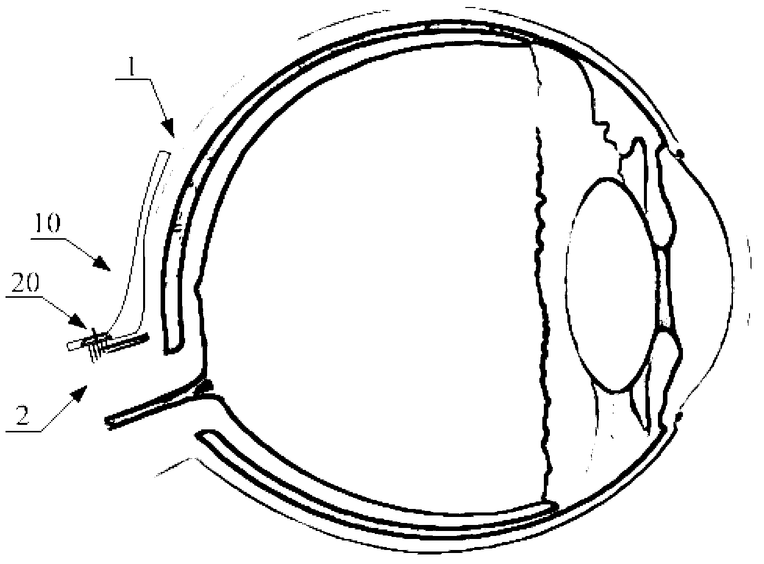
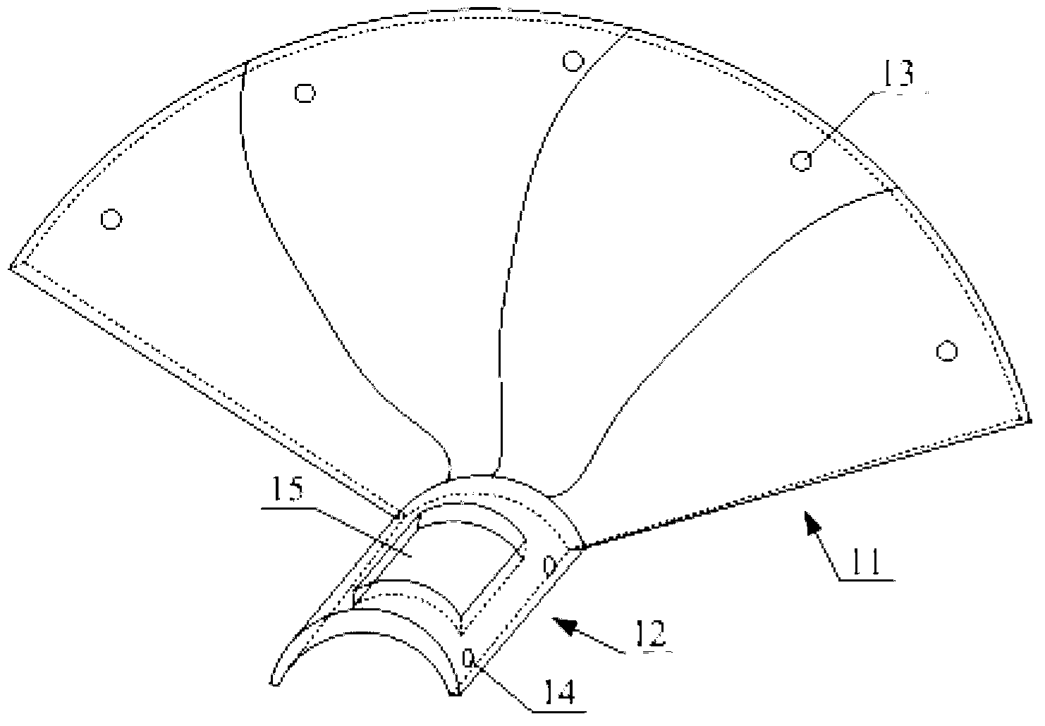
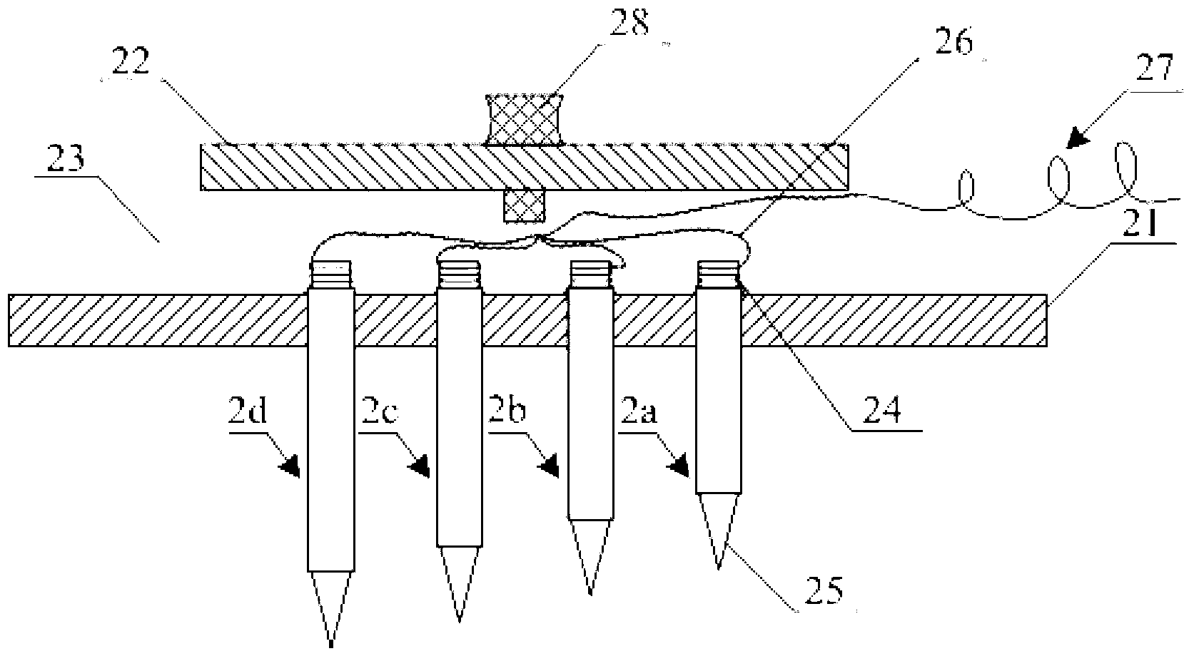
[0026] Such as figure 1 and 2 As shown, in one embodiment of the present invention, the implantable optic nerve interface device of the present invention includes a stimulating electrode array unit 20 and an attachment unit 10 . Wherein, the attachment unit 10 includes a fan-shaped attachment part 11 and a nerve attachment part 12 , the fan-shaped attachment part 11 is attached to the posterior wall of the eyeball 1 , and the nerve attachment part 12 is attached to the optic nerve 2 . The stimulating electrode array unit 20 is fixed on the attachment unit 10, specifically, the nerve attachment part 12 has a hole 15, the stimulating electrode array unit 20 is embedded in the hole 15 and a plurality of electrodes of the stimulating electrode array unit 20 expose the hole 15 to stimulate into the optic nerve 2. The hole 15 on the nerve attachment part 12 in the present embodiment is a rectangular hole; In addition, the edge of the fan-shaped attachment part 11 has a plurality o...


PUM

PropertyMeasurementUnit
Zhang jiaoaaaaaaaaaa
Radiusaaaaaaaaaa

Abstract

The invention discloses an optic nerve implantable interface device. The optic nerve implantable interface device comprises an exciting electrode array unit and an attaching unit, wherein the attaching unit comprises a fan-shaped attaching part and a nerve attaching part; the fan-shaped attaching part is used for being attached onto the rear wall of an eyeball; the nerve attaching part is used for being attached onto the optic nerve; a hole is formed in the nerve attaching part; the exciting electrode array unit is embedded into the hole to be fixed to the attaching unit; and the electrodes of the exciting electrode array unit are exposed from the hole to penetrate into the optic nerve. The fan-shaped attaching part guarantees that the optic nerve implantable interface device can be fixedly attached onto the rear wall of the eyeball long and stably, and the electrodes of the optic nerve implantable interface device can generate uniform multi-layer neuroelectricity excitation on the optic nerve. In addition, the optic nerve implantable interface device has the advantages of high resolution of electrode space, good biocompatibility, easiness in implantation, low operation risk and the like.

Description

technical field [0001] The invention relates to the field of biomedical engineering, in particular to an implantable optic nerve interface device with fan-shaped attachment function. Background technique [0002] Vision is an important way for human beings to understand the objective world, and more than 70% of the information needed for human understanding of the world comes from vision. The formation of vision requires a complete visual pathway, including the refractive system of the eyeball, the retina, the optic nerve and the visual center of the brain. Damage to any part of the visual system may affect the transmission and processing of visual signals, resulting in impaired visual function or blindness, bringing inconvenience and pain to patients' life, study and work. At present, fundus disease has become the primary cause of blindness in developed countries or regions, and it is becoming more and more serious with the aging of the social population, such as age-relat...

Claims


Application Information

Patent Timeline
IPC IPC(8): A61F2/14A61L27/06A61L27/04A61L27/02A61L27/18
Inventor 吴开杰柴新禹任秋实雷旭平陆一樑
Owner SHANGHAI JIAO TONG UNIV
Learn More