Bonding method of belt on belt conveyor

A belt conveyor and bonding method technology, which is applied in the field of metallurgical rolling, can solve the problems of high cost of replacing new products, dismantling the rack, etc., and achieve the effects of reducing maintenance and replacement time, increasing production efficiency, and improving production rhythm

Inactive Publication Date: 2015-03-25
MCC SFRE HEAVY IND EQUIP
View PDF0 Cites 2 Cited by
  • Summary
  • Abstract
  • Description
  • Claims
  • Application Information

AI Technical Summary

Benefits of technology

This new technology allows for better control over conveying materials through open-belly systems without having to stop or take down any equipment during repairs. It also simplifies the process of replacing damaged parts with spare ones instead of discarding them altogether once they are needed again. Overall, this innovation makes it easier and more efficient than previous designs.

Problems solved by technology

This patented technical problem addressed in this patents relates to replacing worn out or damaged leather seals when changing from one type of material (metal) to another without having to break down everything around it all at once during maintenance work.

Method used


Image

  • Bonding method of belt on belt conveyor
  • Bonding method of belt on belt conveyor
  • Bonding method of belt on belt conveyor

Examples


Embodiment Construction

[0019] The present invention will be described in detail below in conjunction with the accompanying drawings and specific embodiments.

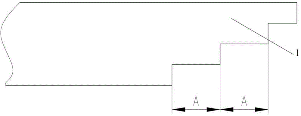
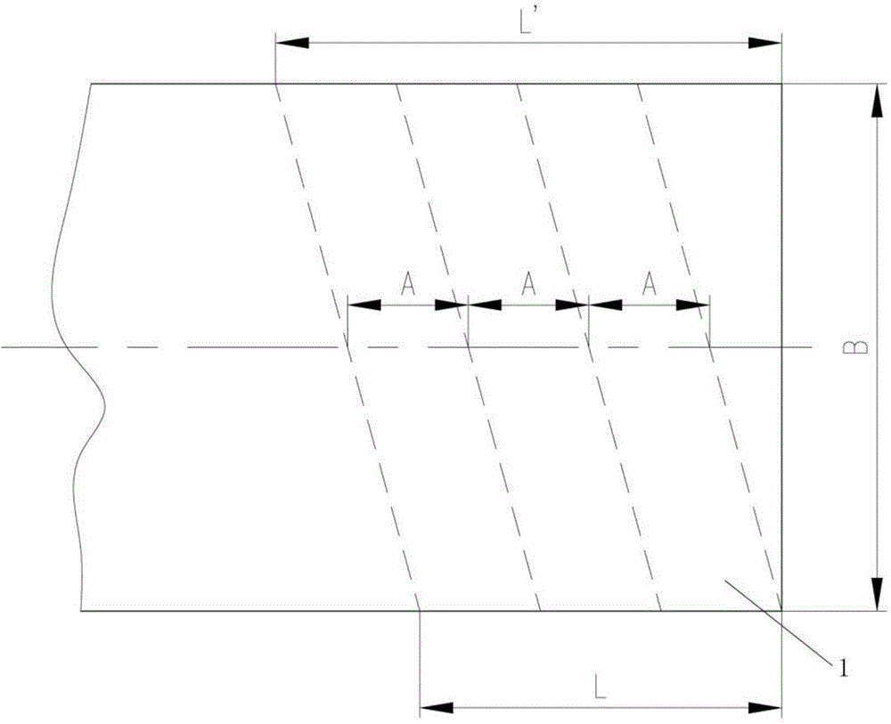
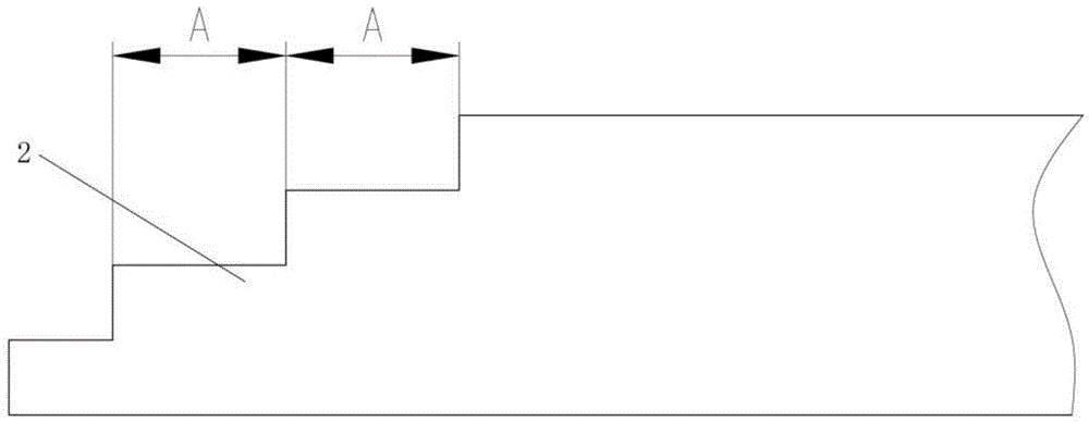
[0020] refer to figure 1 , figure 2 , image 3 , Figure 4 , the preparatory step of the method of the present invention is, in the docking area of ​​the left end joint 1 and the right end joint 2 that need to be docked, a plurality of step steps obliquely intersecting with the longitudinal centerline of the belt are correspondingly provided, wherein the belt width is B, and the belt step The width is A, the length of the inner end of the step bevel (joint length) is L, and the length of the outer end of the step bevel is L'.

[0021] The present invention adopts the oblique section stepped joint form to bond the belt, and adopts a plurality of step steps obliquely intersecting with the longitudinal center line of the belt. The relationship between the number of cut layers X of the joint steps and the number of layers Y of the belt canvas...


PUM


Abstract

The invention discloses a bonding method of a belt on a belt conveyor. The bonding method comprises the following steps: step 1, measuring a butt joint area of a left end joint and a right end joint, calculating a cutting layer number X and a joint length L of the belt, then obtaining a step width A of the belt, cutting redundant belt material by using a blade to obtain a section cutting plane joint step, and grinding a bonding surface; step 2, cleaning the left and right end joints, preparing a synthetic belt adhesive, immediately coating the bonding surface by a layer of adhesive evenly, naturally air drying the adhesive, coating the adhesive for the second time when the adhesive is sticky but not hand sticky, and lapping and bonding the left and right end joints when the adhesive is not hand sticky; step 3, striking from the middle to the surrounding by using a rubber hammer, pressurizing the bonded butt joint area by using a fixture to enable the bonded butt joint area to be smooth and firm. The method disclosed by the invention is economical, applicable, simple and feasible.

Description


Claims


Application Information

Patent Timeline
Owner MCC SFRE HEAVY IND EQUIP
Why Eureka
Try Eureka