Feeding mechanism

A feeding mechanism and feeding technology, which are applied to conveyor objects, conveyor control devices, transportation and packaging, etc., can solve the problems of inaccurate feeding position, low work efficiency, high labor intensity, etc., and achieve accurate feeding position and reduce labor. Strength, the effect of improving work efficiency

Active Publication Date: 2015-03-25
BOZHON PRECISION IND TECH CO LTD
View PDF6 Cites 23 Cited by
  • Summary
  • Abstract
  • Description
  • Claims
  • Application Information

AI Technical Summary

Problems solved by technology

In the prior art, materials are generally reciprocated manually, which is labor-intensive, low-efficiency, and the feeding position is inaccurate, which also affects the smooth progress of the next step of the material.

Method used


Image

  • Feeding mechanism
  • Feeding mechanism
  • Feeding mechanism

Examples


Embodiment Construction

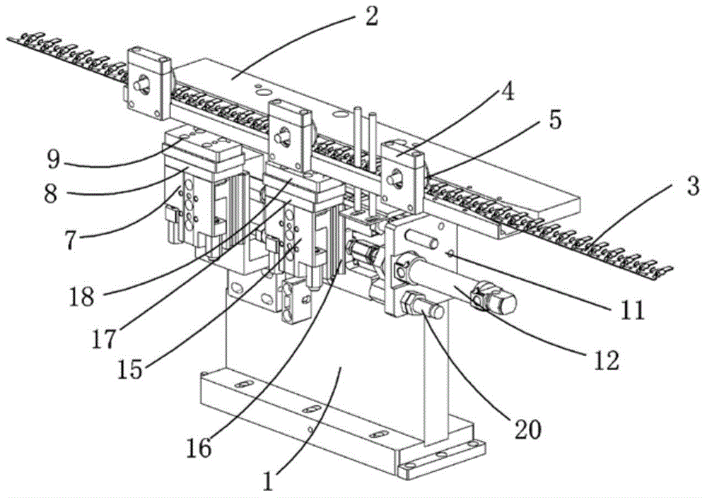
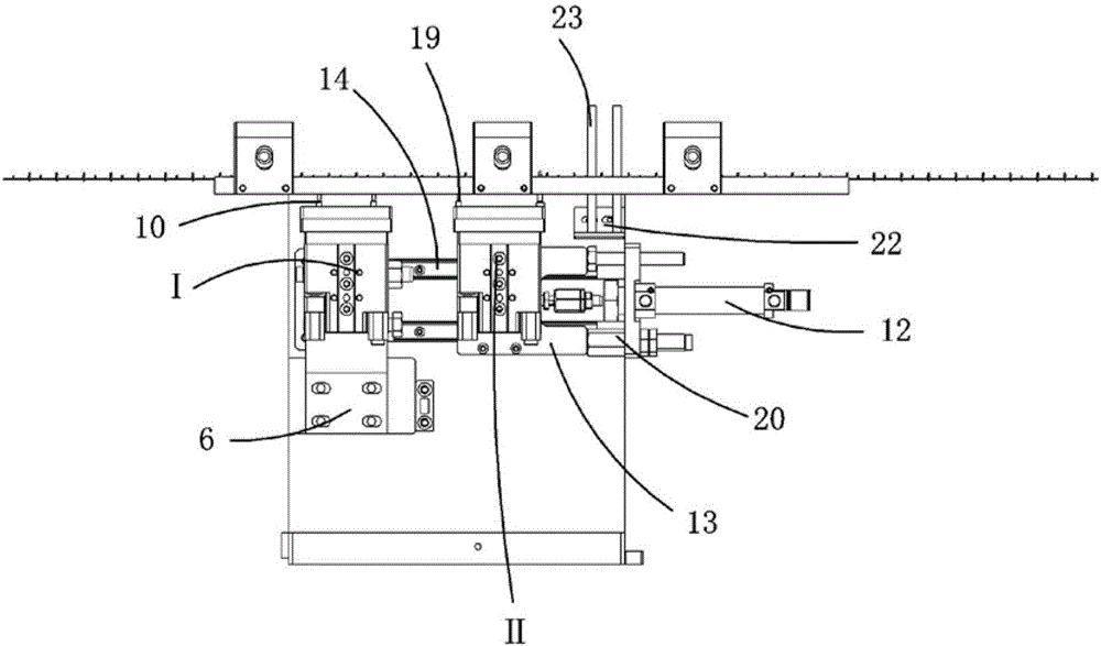
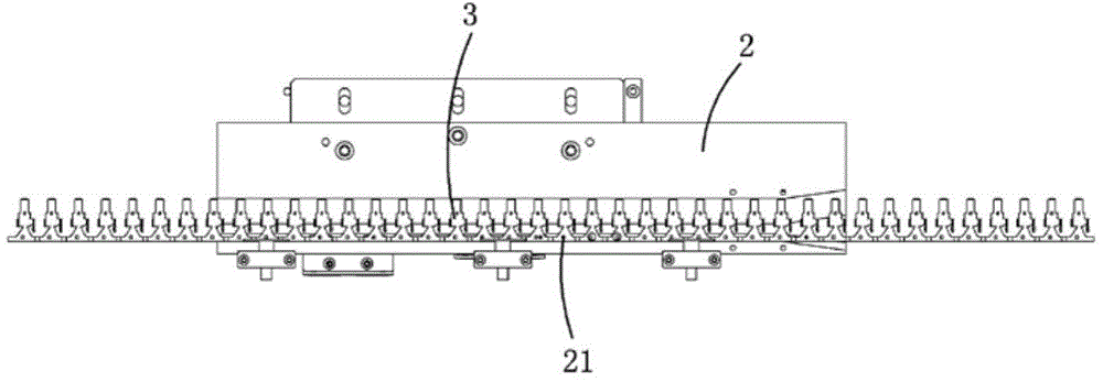
[0021] Examples, see attached Figure 1~4 , a feeding mechanism, which includes a support 1, a drag plate 2 and a material belt 3, the drag plate is installed on the upper part of the support, the material belt is placed on the drag plate, and the drag plate is provided with a Adaptive groove, the material belt is located in the groove, in order to ensure the displacement of the material belt; three sets of roller mounting brackets 4 are installed on the front side of the dragging plate, and the roller mounting brackets are respectively installed on the left end, middle part and right end of the dragging plate Each one, a roller 5 is installed on every group of roller mounts, and the roller can press the material belt to ensure that the material belt moves smoothly.

[0022] On the front side of the support and under the dragging plate, there are respectively installed jacking mechanism I and jacking feeding mechanism II, and the jacking mechanism is located on the left side o...


PUM


Abstract

The invention relates to a feeding mechanism. A material dragging plate is mounted at the upper part of a supporting seat, and a material belt is placed on the material dragging plate; an upward pushing mechanism and a lifting and feeding mechanism are respectively mounted and positioned below the material dragging plate on the front side of the supporting seat; a feeding and lifting cylinder drives feeding and positioning pins to push upwards to be inserted into positioning holes in the material belt, at the moment, the positioning pins on the upward pushing cylinder are in an initial state, the feeding and lifting cylinder can be driven by the feeding cylinder to move to the right on sliding rails and drive the material belt to move forwards, and the feeding and lifting cylinder stops after moving for a certain distance; then the upward pushing cylinder drives the positioning pins to be inserted into the positioning holes in the material belt to be positioned, so that the material belt is prevented from moving; then materials are supplied to the material belt, after the material supplying is completed, the upward pushing cylinder drives the positioning pins to move downwards, the feeding and lifting cylinder also drives the feeding and positioning pins and is driven by the feeding cylinder to move to left to return to an initial position, the materials are transported to a standard operation position, and then the feeding and lifting cylinder drives the feeding positioning pins to perform second feeding under the driving of the feeding cylinder. The feeding mechanism can realize reciprocating feeding and supplying of the materials.

Description

Technical field: [0001] The invention relates to the field of feeding mechanism equipment, and more specifically relates to a feeding mechanism capable of reciprocating feeding with material belt feeding. Background technique: [0002] In the assembly line operation process of the production workshop, the material is generally placed on the material belt, and the material belt is generally placed on the support plate. Sometimes the material belt needs to be able to move forward to convey the material when it is used, and it stops after moving forward for a certain distance, and then the material Belt feeding, after the feeding is completed, the material belt returns to the initial position for the second feeding, so that the material can be fed back and forth, which can improve work efficiency and the feeding position is accurate. In the prior art, materials are generally reciprocated manually, which is labor-intensive, low in efficiency, and the feeding position is inaccura...

Claims


Application Information

Patent Timeline
Patent Type & Authority Applications(China)
IPC IPC(8): B65G47/82B65G47/74B65G43/00
Inventor 吕绍林陈小刚陈骅张长辉
Owner BOZHON PRECISION IND TECH CO LTD
Why Eureka
Try Eureka