
Passenger Elevator Energy Saving Device

An energy-saving device and elevator technology, which is applied to elevators in buildings, transportation and packaging, and home heating, etc., can solve the problems of inconsistent slogans of energy saving and consumption reduction, affecting elevator comfort, and elevator consumption of large power, etc. Achieve the effect of saving energy consumption, reducing power consumption and improving comfort

Active Publication Date: 2017-02-01
CIVIL ELEVATOR
View PDF14 Cites 0 Cited by
  • Summary
  • Abstract
  • Description
  • Claims
  • Application Information

AI Technical Summary

Problems solved by technology

Today's life advocates energy saving and environmental protection, but the existing elevators need electric support for operation, lighting and ventilation, and elevators need to consume a lot of electricity every day. Such elevators undoubtedly do not conform to the slogan of energy saving and consumption reduction.
Furthermore, during the winter wind change process of the existing elevator, the air blown into the inside of the car is all cold air, and the cold air is directly blown from the top down on the person's body, which is easy to get cold and sick.
If heating equipment is used to heat the air, power resources will undoubtedly be used, resulting in a large consumption of power resources
Moreover, many parts of the existing elevators are installed on the car roof or the car floor, which will be accompanied by a large amount of oil smell during use. During the action of the elevator ventilation fan, a large amount of air with oil smell will be Drum into the interior of the car, affecting the comfort of people taking the elevator

Method used


Image

  • Passenger Elevator Energy Saving Device

Examples


Embodiment Construction

[0012] The present invention will be further described below in conjunction with the accompanying drawings and embodiments, but not as a basis for limiting the present invention.

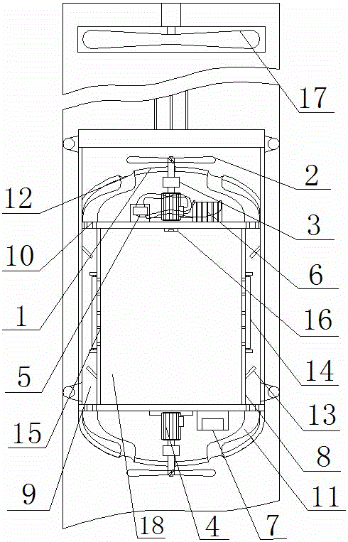
[0013] Passenger elevator energy-saving device, as attached figure 1 As shown, the energy-saving device is installed on the elevator car 18 of the elevator, and specifically includes a fairing 1 arranged on the upper part of the car roof and the lower part of the car bottom plate. The fairing 1 is a hemispherical mechanism, and the fairing 1 covers A generator mechanism 4 is installed on the upper surface of the car roof and the lower bottom surface of the car bottom plate, each generator mechanism 4 is connected with a speed-increasing mechanism 3, and the speed-increasing mechanism 3 is provided with the outside of the fairing 1. The rotating blades 2 are connected, and the two power generating mechanisms 4 are connected to the charging equipment 5 on the car roof. The charging equipment 5 is conn...


PUM


Abstract

The invention discloses an energy saver of a passenger elevator. The energy saver comprises rectifying covers arranged on the upper portion of the top plate of a car and the lower portion of the bottom plate of the car, the top plate and the bottom plate of the car covered by the rectifying covers are provided with generator mechanisms, the generator mechanisms are connected with speedup mechanisms, the speedup mechanisms are connected with rotary blades outside the rectifying covers, the generator mechanisms are connected with a charging device on the top plate of the car, the charging device is connected with an electric storage device beside, and the electric storage device is connected with an electrical control part on the bottom plate of the car; vertical partitions are arranged on the inner sides of the side walls of the car, air passages are reserved between the side walls of the car and the vertical partitions, the top plate and the bottom plate of the car are provided with air inlets corresponding to two ends of the air passages, and the air inlets are connected with air inlet holes of the rectifying covers through air inlet conduits; two inclined stoppers are arranged on the side walls of the car and / or the vertical partitions at intervals corresponding to the air passages, and the vertical partitions are provided with vent holes. The ventilation of the elevator does not need power support, so that energy consumption is saved.

Description

technical field [0001] The invention relates to an energy-saving device, in particular to an energy-saving device for a passenger elevator. Background technique [0002] Elevators have been widely used in people's daily life, especially in high-rise buildings. In today's life, energy saving and environmental protection are advocated, but the existing elevators need electric support for operation, lighting and ventilation. Elevators consume a lot of electricity every day. Such elevators are undoubtedly inconsistent with the slogan of energy saving and consumption reduction. In addition, during the air change process of the existing elevator in winter, the air blown into the car is cold air, and the cold air is directly blown down on the person from the top, which is easy to use and get sick from the cold. If a heating device is used to heat the air, power resources will undoubtedly be used, resulting in a large consumption of power resources. In addition, many parts of the ...

Claims


Application Information

Patent Timeline
Patent Type & Authority Patents(China)
IPC IPC(8): B66B11/02F24F7/04
CPCB66B11/00B66B11/024
Inventor 吴荣杨轶平应后明
Owner CIVIL ELEVATOR
Learn More