Lace weaving device in shuttleless loom
A shuttleless loom and lace technology, applied in looms, auxiliary equipment for weaving, weaving, etc., can solve the problems of inability to weave lace fabrics and meet the diversification of the market, achieve rich diversification, promote development, increase The effect of life force
- Summary
- Abstract
- Description
- Claims
- Application Information
AI Technical Summary
Problems solved by technology
Method used
Image

Examples
Embodiment Construction
[0018] The present invention will be described in detail below with reference to the accompanying drawings and in combination with embodiments.
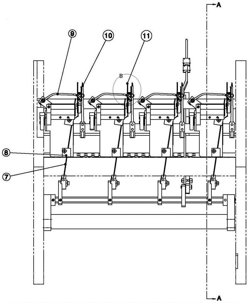
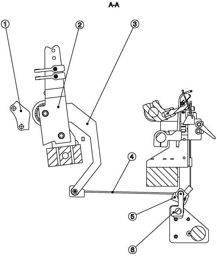
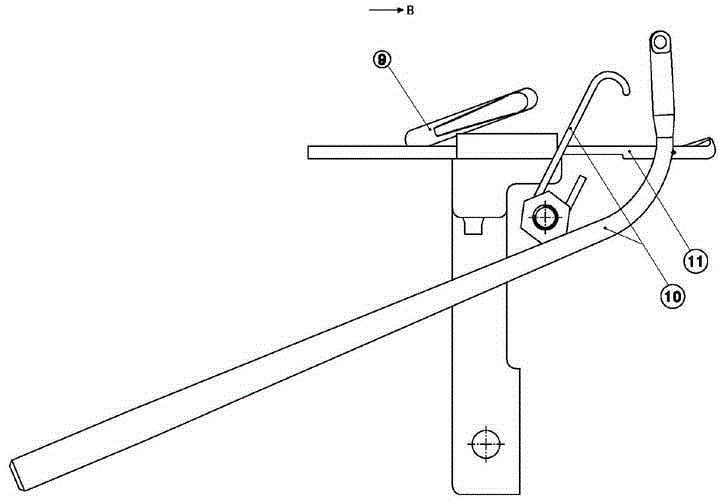
[0019] refer to Figure 1 to Figure 3 As shown, a lace weaving device in a shuttleless loom includes a flower chain piece 1, the outer curve of the flower chain piece 1 cooperates with the bearing outer ring on the blade set 2 to form a cam driving roller structure, and drives the blades The group 2 moves up and down, the blade group 2 drives and connects one end of the connecting rod 3, the up and down movement of the blade group 2 drives the connecting rod 3 to move up and down, and the other end of the connecting rod 3 is connected to the thin guide rod 4 through the rotating pin, and the thin guide rod 4 The other end of the connecting block 5 is fixed in the connecting block 5, and the up and down movement of the thin guide rod 4 drives the connecting block 5 to swing slightly, and the connecting block 5 transmits torque to the ...
PUM
 Abstract
Description
Claims
Application Information