Well completing tester and system thereof

A tester and cavity technology, applied in the field of well completion tester and its system, can solve the problems of complicated test process, inconvenient use, inconvenient use, etc., and achieve the effect of simple test process and easy use

Active Publication Date: 2015-03-25
CHINA PETROLEUM & CHEM CORP +1
View PDF10 Cites 4 Cited by
  • Summary
  • Abstract
  • Description
  • Claims
  • Application Information

AI Technical Summary

Problems solved by technology

Therefore, the test process is too complicated and not easy to use
[0006] To sum up, in the existing well comp...

Method used


Image

  • Well completing tester and system thereof
  • Well completing tester and system thereof
  • Well completing tester and system thereof

Examples


Embodiment 1

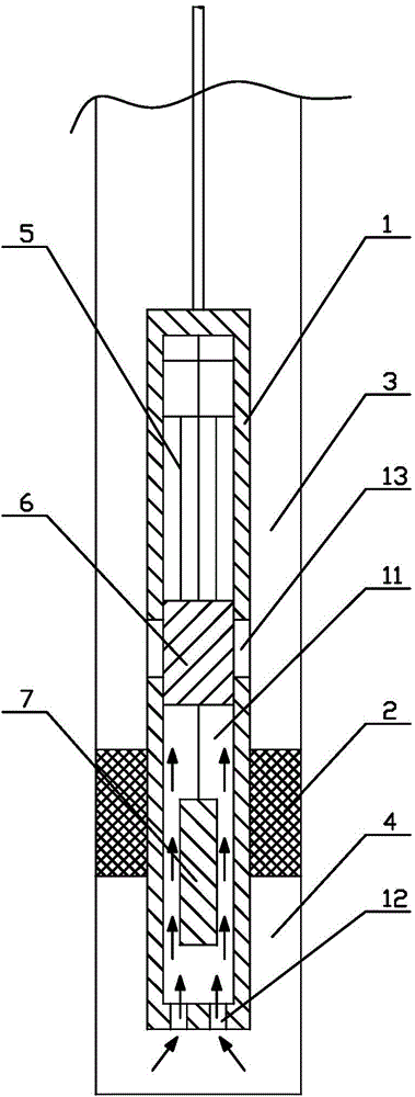
[0074] Such as figure 1 and figure 2 As shown, the completion tester provided in this embodiment includes: a first shell 1 with a flow channel cavity 11 formed inside; a packing device 2 for setting outside the first shell 1, And the isolation device 2 is used to divide the downhole into the upper cavity 3 and the lower cavity 4; the driving device 5 arranged in the flow channel cavity 11 and the sliding rod 6 connected with the driving device 5, the driving device 5 drives the sliding rod 6 moves in the axial direction; the test device 7 arranged in the first housing 1, the test device 7 is located below the slide bar 6; formed in the lower part of the first housing 1 and connected with the flow channel cavity 11 and the lower cavity 4 The liquid inlet 12 connected with each other, and the liquid outlet 13 formed on the first shell 1 above the isolation device 2 and connected with the flow channel cavity 11 and the upper cavity 3; wherein, the slide bar 6 can Driven by the...

Embodiment 2

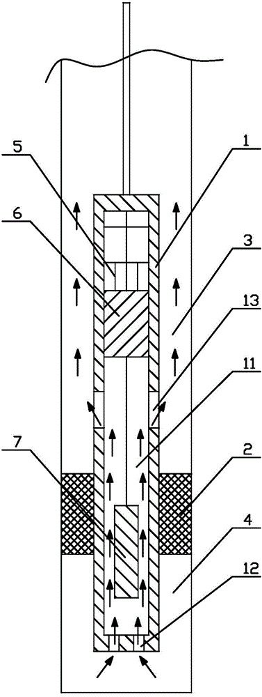
[0083] Such as image 3 As shown, the completion tester provided in this embodiment includes: a first shell 1 with a flow channel cavity 11 formed inside; a packing device 2 for setting outside the first shell 1, And the isolation device 2 is used to divide the downhole into an upper cavity 3 and a lower cavity 4 (the dotted line in the figure indicates that the isolation device 2 is in an open state and is attached to the well wall); it is installed in the flow channel cavity The driving device 5 in the body 11 and the sliding rod 6 connected with the driving device 5, the driving device 5 drives the sliding rod 6 to move axially; the testing device 7 arranged in the first housing 1, the testing device 7 is located on the sliding rod 6 The lower part of the first casing 1 is formed with a liquid inlet 12 that communicates with the flow channel cavity 11 and the lower cavity 4, and the first casing 1 is located above the isolation device 2 and is formed with a flow channel cav...

Embodiment 3

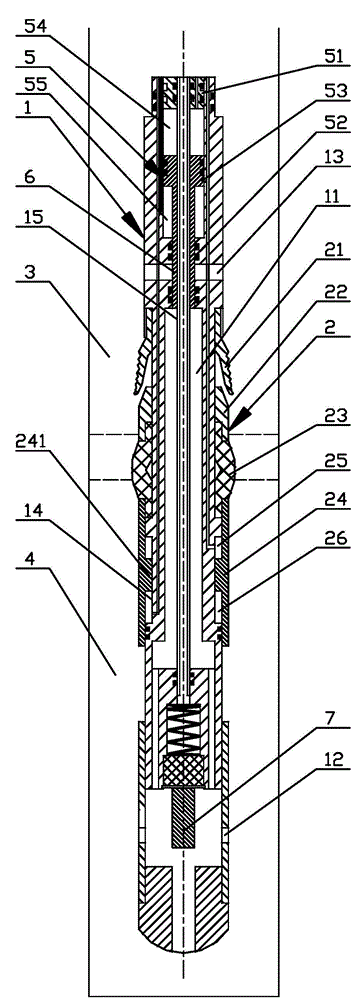
[0111] Such as Figure 4 As shown, a well completion testing system is provided in this embodiment, including an auxiliary controller and the completion tester described in Embodiment 2 above; the auxiliary controller includes a second housing 8 with a mounting cavity, and along The control circuit device 9 and the hydraulic oil tank 91 are sequentially arranged in the second housing 8 axially downward; wherein, the lower end of the second housing 8 is connected to the upper end of the first housing 1, and the control circuit device 9 is connected to the testing device 7 The hydraulic oil tank 91 is connected with the first cavity 54 , the second cavity 55 , the third cavity 25 and the fourth cavity 26 respectively.

[0112] The specific working process and beneficial effects of the well completion tester in the well completion test system provided in this embodiment have been fully described in Embodiment 2, and will not be described again.

[0113] The control circuit devic...


PUM


Abstract

The invention provides a well completing tester which comprises a first shell, a packing device, a drive device, a sliding rod, a testing device, a liquid inlet and a liquid outlet. A runner cavity is formed in the first shell. The packing device is arranged outside the first shell and used for separating the down-hole portion into an upper cavity and a lower cavity. The drive device and the sliding rod connected with the drive device are arranged in the runner cavity. The drive device drives the sliding rod to move in the axial direction. The testing device is arranged in the first shell and located below the sliding rod. The liquid inlet is formed in the lower portion of the first shell and communicated with the runner cavity and the lower cavity. The liquid outlet is formed in the portion, located above the packing device, of the first shell and communicated with the runner cavity and the upper cavity. The drive device controls the sliding rod to move in the axial direction so that the upper cavity and the lower cavity can be communicated or disconnected to open or close the well; then the testing device is utilized for recording the dynamic change process of the down-hole pressure, so that well completing testing is finished, the testing process is simple, and the tester is convenient to use. The invention further provides a well completing testing system.

Description

technical field [0001] The invention relates to a well completion tester and a system thereof, belonging to the technical field of well completion testing. Background technique [0002] As we all know, well completion testing is the oil and gas flow testing work on favorable or possible oil and gas bearing formations after well completion. The existing completion testing technology at home and abroad generally adopts the completion testing technology of drill pipe or tubing, which is a testing technology that combines various testing tools according to the testing purpose and the physical properties of the testing interval. [0003] At present, the string conveying type test tool is generally used in China. For example: Annulus Pressure Response (APR) test technology and Multi-Flow Evaluator (MFE) test technology. Both processes connect supporting tools through oil pipes or drill pipes, run them downhole, and control the downhole tools on the ground, so as to achieve the p...

Claims


Application Information

Patent Timeline
IPC IPC(8): E21B47/06E21B33/127
CPCE21B33/127E21B47/06
Inventor 张同义毛军杜娟庞伟贺英姚志良吴琼
Owner CHINA PETROLEUM & CHEM CORP
Why Eureka
Try Eureka