Hydraulic power control system for hydraulic plug type lifting system

A control system and hydraulic power technology, applied in fluid pressure actuators, servo motors, mechanical equipment, etc., can solve problems such as slow lifting leg speed, achieve the effects of accelerating telescopic speed, ensuring stability, and increasing lifting speed

Active Publication Date: 2015-03-25
WUHAN MARINE MACHINERY PLANT
View PDF6 Cites 8 Cited by
  • Summary
  • Abstract
  • Description
  • Claims
  • Application Information

AI Technical Summary

Problems solved by technology

[0006] In order to solve the problem of the slow lifting speed of the legs of the hydraulic bolt-type lifting mechanism in the prior art, the embodiment of the present invention provides a hydraulic power control system of the hydraulic bolt-type lifting system

Method used


Image

  • Hydraulic power control system for hydraulic plug type lifting system
  • Hydraulic power control system for hydraulic plug type lifting system
  • Hydraulic power control system for hydraulic plug type lifting system

Examples


Embodiment 1

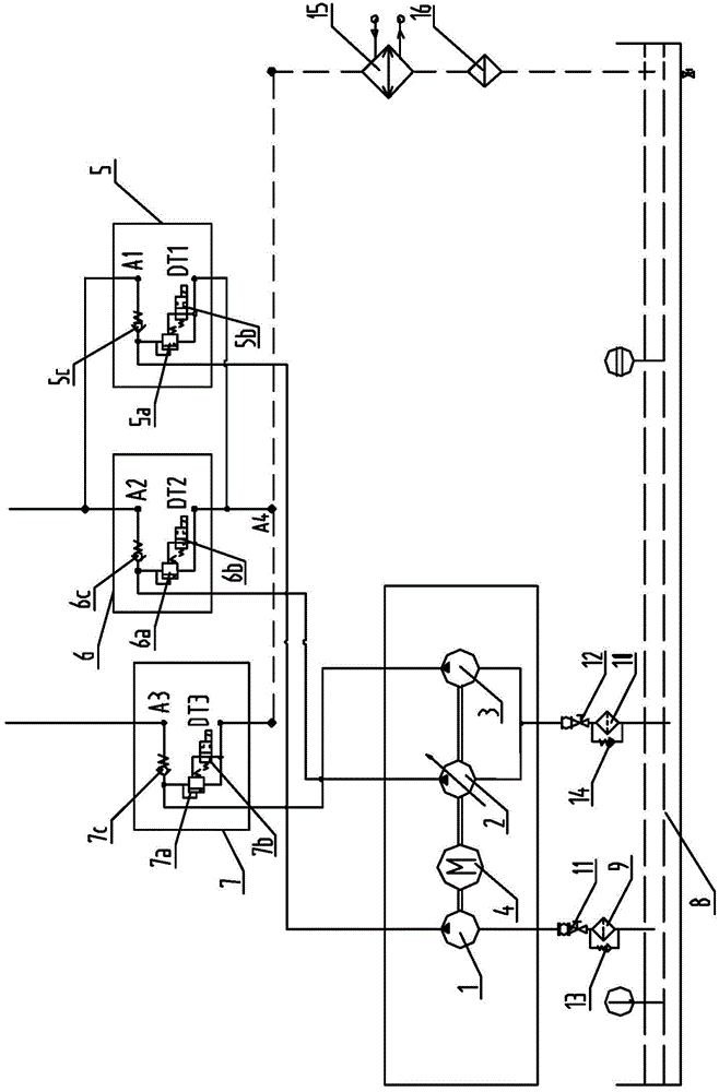
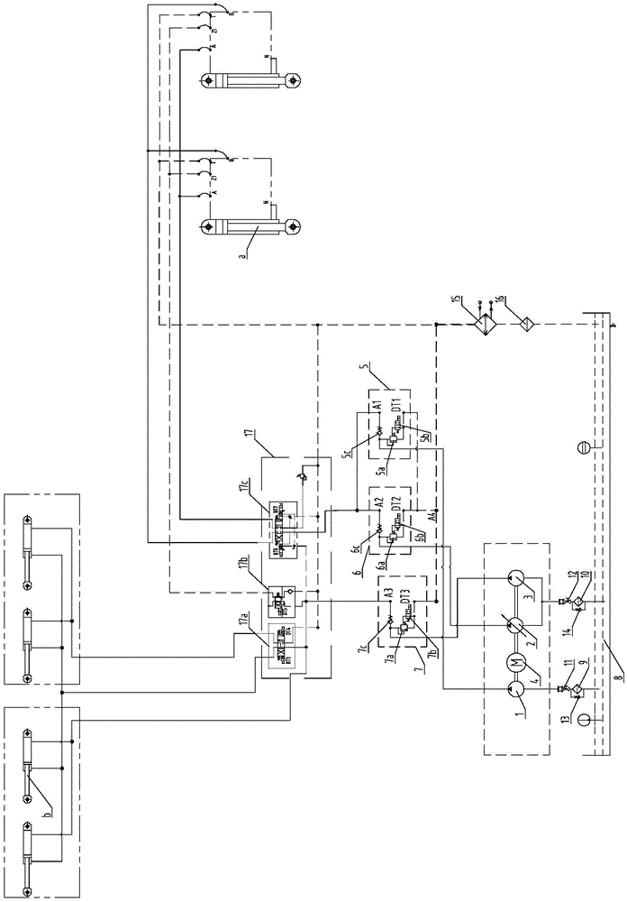
[0029] An embodiment of the present invention provides a hydraulic power control system of a hydraulic bolt-type lifting system, such as figure 1 As shown, the hydraulic power control system includes a hydraulic drive assembly, a first unloading circuit 5, a second unloading circuit 6, a third unloading circuit 7 and a main control valve 17. The hydraulic drive assembly includes a first hydraulic pump 1, The second hydraulic pump 2, the third hydraulic pump 3 and the driving device 4 for powering the first hydraulic pump 1, the second hydraulic pump 2 and the third hydraulic pump 3, the first unloading circuit 5 includes a first pilot relief valve 5a and the first two-position two-way solenoid valve 5b, the second unloading circuit 6 includes the second pilot relief valve 6a and the second two-position two-way solenoid valve 6b, the third unloading circuit 7 includes the third pilot relief valve 7a and the third two-position two-way solenoid valve 7b.

[0030] The oil outlet ...

Embodiment 2

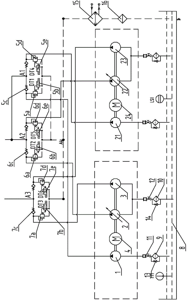
[0052] An embodiment of the present invention provides a hydraulic power control system, such as image 3 As shown, the difference between the hydraulic power control system and the first embodiment is that the hydraulic power control system can also include a second hydraulic power control system including a second hydraulic drive assembly, a fourth unloading circuit, a fifth unloading circuit and a second hydraulic power control system. Six unloading circuits, the second hydraulic power control system includes the second hydraulic drive assembly, the fourth unloading circuit, the fifth unloading circuit and the sixth unloading circuit and the hydraulic drive assembly, the first unloading circuit 5, the second unloading circuit The unloading circuit 6 and the third unloading circuit 7 have the same structure, and the second hydraulic drive assembly includes a fourth hydraulic pump 21, a fifth hydraulic pump 22, a sixth hydraulic pump 23 and a second driving device 24, and the ...


PUM


Abstract

The invention discloses a hydraulic power control system for a hydraulic plug type lifting system and belongs to the field of ocean engineering. The hydraulic power control system comprises a hydraulic drive assembly, a first unloading loop, a second unloading loop and a third unloading loop. The hydraulic drive assembly comprises a first hydraulic pump, a second hydraulic pump, a third hydraulic pump and a drive device which provides power for the first hydraulic pump, the second hydraulic pump and the third hydraulic pump. The first unloading loop comprises a first pilot overflow valve and a first two-position two-way electromagnetic valve. The second unloading loop comprises a second pilot overflow valve and a second two-position two-way electromagnetic valve. The third unloading loop comprises a third pilot overflow valve and a third two-position two-way electromagnetic valve. When the hydraulic power control system is used for lifting pile legs, the first hydraulic pump and the second hydraulic pump provide oil for a lifting oil cylinder, the oil supplied to the lifting oil cylinder is increased, the telescoping speed of the lifting oil cylinder is increased, and then the lifting speed of the pile legs is increased.

Description

technical field [0001] The invention relates to the field of marine engineering, in particular to a hydraulic power control system of a hydraulic bolt type lifting system. Background technique [0002] The jack-up offshore platform mainly includes multiple legs, lifting mechanism and platform main body. The lifting mechanism is the key core equipment of the jack-up offshore platform. The lifting mechanism is installed at the well of the pile legs, and the lifting mechanism is driven by the hydraulic power control system. Thereby, the relative movement between the main body of the platform and the legs is realized. [0003] The hydraulic bolt-type lifting system realizes the relative movement between the platform body and the legs through the cooperation of the lifting cylinder and the bolt cylinder. The hydraulic power control system of the existing hydraulic bolt-type lifting mechanism includes two hydraulic pumps, one of which is used to drive the bolt cylinder, another h...

Claims


Application Information

Patent Timeline
Patent Type & Authority Applications(China)
IPC IPC(8): F15B11/17
CPCF15B11/17
Inventor 田崇兴黄冠乔
Owner WUHAN MARINE MACHINERY PLANT
Why Eureka
Try Eureka