
A self-circulating lubrication method and device for a positive and negative alternate rotation vertical reducer

A forward and reverse rotation, reducer technology, used in transmission parts, gear lubrication/cooling, belts/chains/gears, etc. The effect of reducing size and weight, structure and appearance, and improving overall performance

Active Publication Date: 2017-08-11
GUIZHOU QUNJIAN PRECISION MACHINERY
View PDF6 Cites 0 Cited by
  • Summary
  • Abstract
  • Description
  • Claims
  • Application Information

AI Technical Summary

Problems solved by technology

The oil-filled oil bath lubrication method is to fill the gearbox with lubricating oil to realize the lubrication of the upper parts of the reducer. The disadvantage of this lubrication method is: since all the reduction gears and moving parts are immersed in the lubricating fluid The rotation resistance is increased, so that the power loss of the reducer is large, and the filling amount of lubricating oil is large, the cost is high, and the weight of the reducer is large
The external circulation lubrication method is to add a set of circulating lubrication system outside the reducer, and complete the lubrication of the upper parts of the reducer through the external circulating lubrication system of the reducer. The disadvantages of this lubrication method are: high cost, large volume and complex structure

Method used


Image

  • A self-circulating lubrication method and device for a positive and negative alternate rotation vertical reducer
  • A self-circulating lubrication method and device for a positive and negative alternate rotation vertical reducer
  • A self-circulating lubrication method and device for a positive and negative alternate rotation vertical reducer

Examples


Embodiment

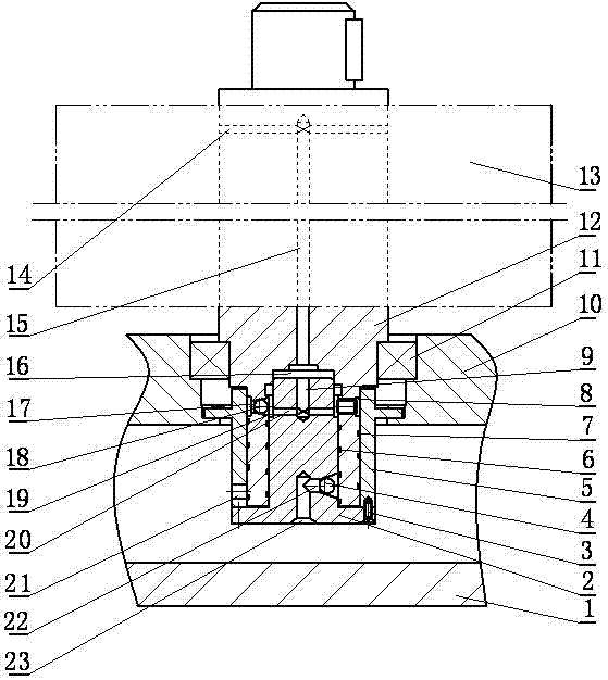
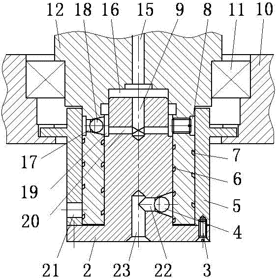
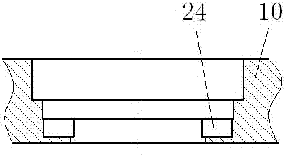
[0026] During specific implementation, the bearing seat 10 is fixed on the bottom of the box body 1 , and the bearing 11 on the input shaft 12 cooperates with the hole on the bearing seat 10 .

[0027] A plurality of outer helical grooves 7 are processed on the outer circle of the lower end of the input shaft 12, and a plurality of inner helical grooves 6 are processed in the hole. The rotation directions of the outer helical grooves 7 and the inner helical grooves 6 are opposite. When the input shaft 12 rotates clockwise, the outer helical groove 7 works to pump oil; when the input shaft 12 rotates counterclockwise, the inner helical groove 6 works to pump oil; when the outer helical groove 7 is left-handed, When the internal helical groove 6 is right-handed, the working pump oil direction is just opposite.

[0028] In the present invention, the pump core 2 and the pump sleeve 5 are connected as a whole by the screw 3, and cooperate with the outer circle and the hole where th...


PUM


Abstract

The invention discloses a self-circulation lubricating method and device of a vertical gear reducer with a forward-reverse alternative rotation function. In the method, the bottom of an input shaft of the gear reducer is in the shape of a round tube, a section of an inner helix groove is arranged in the inner wall of the round tube, and an inner pump composed of a pump core is arranged in the round tube; in addition, the outer circle of the round tube of the bottom of the gear reducer is provided with a section of outer helix groove, and the outer helix groove is sleeved with a pump sleeve to form an outer pump; meanwhile, a main oil passage allowing lubricating oil to ascend is arranged in the input shaft, when the input shaft rotates forwards or reversely, the lubricating oil at the bottom of a case of the gear reducer is pumped to the upper portion of a gear reducer part through the inner pump or outer pump so as to lubricate the part of the upper portion of the gear reducer, and then the lubricating oil returns to the bottom of the case, so that self-circulation lubrication of the gear reducer is realized. The self-circulation lubrication mode different from an existing full-oil type oil bath lubricating mode and an outer-circulation lubricating mode is adopted, the structure and the appearance of the gear reducer are simpler, and size and weight of the gear reducer can be reduced. Overall performance of the gear reducer is improved.

Description

technical field [0001] The invention relates to a self-circulating lubrication method and device for a forward and reverse alternately rotating vertical reducer, belonging to the technical field of reducer lubrication. Background technique [0002] There are mainly two types of existing reducer lubrication methods, one is full oil oil bath lubrication method, and the other is external circulation lubrication method. The oil-filled oil bath lubrication method is to fill the gearbox with lubricating oil to realize the lubrication of the upper part of the reducer. The disadvantage of this lubrication method is: since all the reduction gears and moving parts are immersed in the lubricating fluid The increased rotation resistance causes a large power loss of the speed reducer, and the filling amount of lubricating oil is large, the cost is high, and the weight of the speed reducer is heavy. The external circulation lubrication method is to add a set of circulating lubrication sy...

Claims


Application Information

Patent Timeline
Patent Type & Authority Patents(China)
IPC IPC(8): F16H57/04
CPCF16H57/043F16H57/0434F16H57/0435F16H57/0436
Inventor 王建军白彦伟王江杨季玲
Owner GUIZHOU QUNJIAN PRECISION MACHINERY
Learn More