Air-conditioner air supplier and floor air conditioner

An air supply device and air-conditioning technology, which is applied in air-conditioning systems, space heating and ventilation, heating methods, etc., can solve the problems of reduced wind speed, low heat exchange wind speed, and high noise, so as to improve the air volume and air supply The effect of increasing the distance, increasing the flow speed of the airflow, and reducing the noise of the air supply

Active Publication Date: 2015-03-25
HAIER GRP CORP +1
View PDF6 Cites 13 Cited by
  • Summary
  • Abstract
  • Description
  • Claims
  • Application Information

AI Technical Summary

Problems solved by technology

[0005] but, figure 1 In the shown vertical air conditioner, since the wind after heat exchange by the heat exchanger 5 can only be sent out from the heat exchange air ducts 15, 16 and 17, there is a lack of guidance between each heat exchange air duct and the heat exchanger 5. The structure of the air flow makes the heat exchange air flow disorderly under the air-conditioning air supply device 1 and easily form a vortex, especially the vortex is more serious under the air guide body 11 located at the front end (such as figure 1 Indicated by the air flow direction indicated by the middle arrow), the wind speed is reduced, so that part of the heat exchange air cannot flow smoothly to each heat exchange air duct, and the air intake in the circumferential direction of each heat exchange air duct is uneven, the air volume at the bottom is large, and the middle Small air volume above
This will make the heat exchange air sent from the heat exchange air duct low in speed and large in pressure loss, which not only affects the air volume of the non-heat exchange air introduced from the non-heat exchange air inlet 42, but also reduces the air volume and air supply of the air conditioner. distance, and makes the noise larger during the air supply process

Method used


Image

  • Air-conditioner air supplier and floor air conditioner
  • Air-conditioner air supplier and floor air conditioner
  • Air-conditioner air supplier and floor air conditioner

Examples


Embodiment Construction

[0026] The technical solutions of the present invention will be further described in detail below in conjunction with the accompanying drawings and specific embodiments.

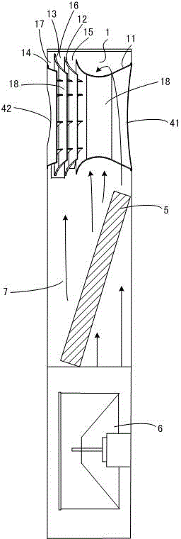
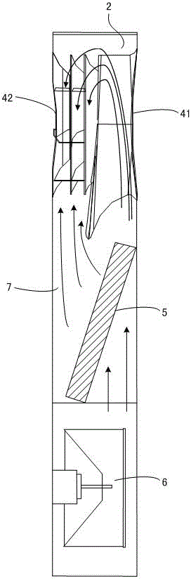
[0027] First of all, a brief description of the technical terms involved in this specific embodiment: when referring to the front or back of each structural component, it is defined by the position of the structural component relative to the user under normal use When describing the arrangement position of multiple structural parts before or after, it is also the definition of the position of the device composed of multiple structural parts relative to the user in normal use. The following heat exchange wind refers to the wind from the inside of the air conditioner after heat exchange by the heat exchanger; the non-heat exchange wind refers to the wind from the environment space where the air conditioner is located, which is relative to the heat exchange wind and does not directly come from Part of the wind ...


PUM


Abstract

The invention discloses an air-conditioner air supplier and a floor air conditioner. The air-conditioner air supplier comprises a plurality of hollow air guiders with air inlets and air outlets, the air guiders are arranged front and back in sequence and through air passages running through front and back are formed between the air guiders. Heat exchange air passages are formed between every two adjacent air guiders, a supplier mixed air outlet and a supplier non-heat-exchange air inlet are formed in the front end and the rear end of the air-conditioner air supplier respectively, and drainage portions extending outwards away from the through air passages and guiding the airflow into the heat exchange at least form the front air guiders of the mixed air outlet in the air guiders. The air guiders of the air-conditioner air supplier are provided with the drainage portions, the airflow can be stably, smoothly and orderly guided into the heat exchange air passages of the supplier, flow velocity of the airflow is increased and air feed noise is reduced.

Description

technical field [0001] The invention belongs to the technical field of air conditioning, and in particular relates to an air supply device for an air conditioner and a vertical air conditioner with the device. Background technique [0002] When the existing vertical air conditioner is blowing air, the wind after heat exchange by the heat exchanger is directly blown out from the air outlet provided on the air conditioner under the action of the internal fan, and all the blown wind is heat exchange air. Generally, no additional air supply device is provided between the heat exchanger and the air outlet. One disadvantage of this kind of air supply air is that all the air sent out is heat exchange air, the air volume is less, and the indoor air circulation speed is slow; another disadvantage is that the air sent out is not soft enough, especially in the cooling mode, the cool wind blown out Blowing directly onto the user makes the user feel uncomfortable. [0003] In order to ...

Claims


Application Information

Patent Timeline
Patent Type & Authority Applications(China)
IPC IPC(8): F24F13/08
CPCF24F1/0003F24F13/08F24F13/24
Inventor 王永涛贾广芬王晓刚
Owner HAIER GRP CORP
Why Eureka
Try Eureka