Conductor sag monitoring device based on laser distance measurement and monitoring methods

A technology of laser distance measurement and conductor sag, which is applied in the direction of measuring devices, optical devices, instruments, etc., can solve the problems that the distance between the conductor and the ground needs to be checked manually, cannot be checked online in real time, and the inspection period is long. The effect of equipment inspection ability, improvement of line quality and automation level of line operation and maintenance, and guarantee of safe and reliable operation

Inactive Publication Date: 2015-03-25
SHANGHAI ELECTRIC CABLE RES INST +2
View PDF12 Cites 6 Cited by
  • Summary
  • Abstract
  • Description
  • Claims
  • Application Information

AI Technical Summary

Problems solved by technology

[0010] In view of the shortcomings of the prior art described above, the purpose of the present invention is to provide a wire sag monitoring device and monitoring method based on laser ranging, which is used to solve the pr

Method used


Image

  • Conductor sag monitoring device based on laser distance measurement and monitoring methods
  • Conductor sag monitoring device based on laser distance measurement and monitoring methods

Examples


Embodiment Construction

[0047] The implementation of the present invention will be illustrated by specific specific examples below, and those skilled in the art can easily understand other advantages and effects of the present invention from the contents disclosed in this specification.

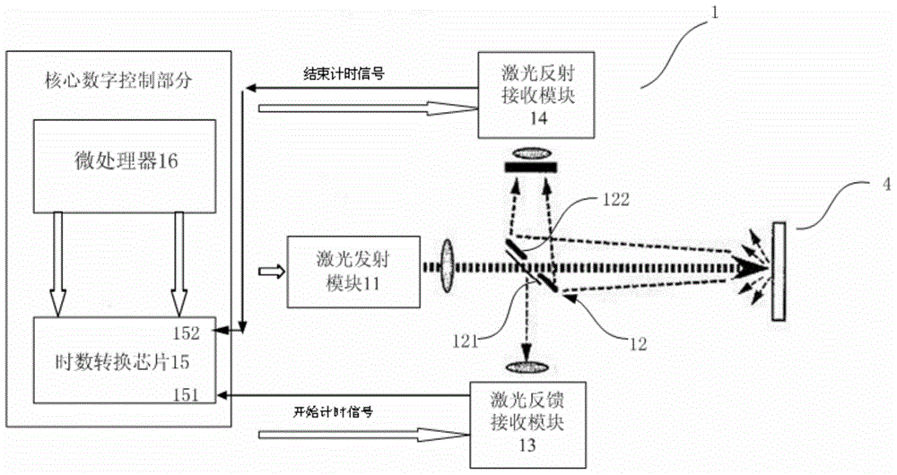
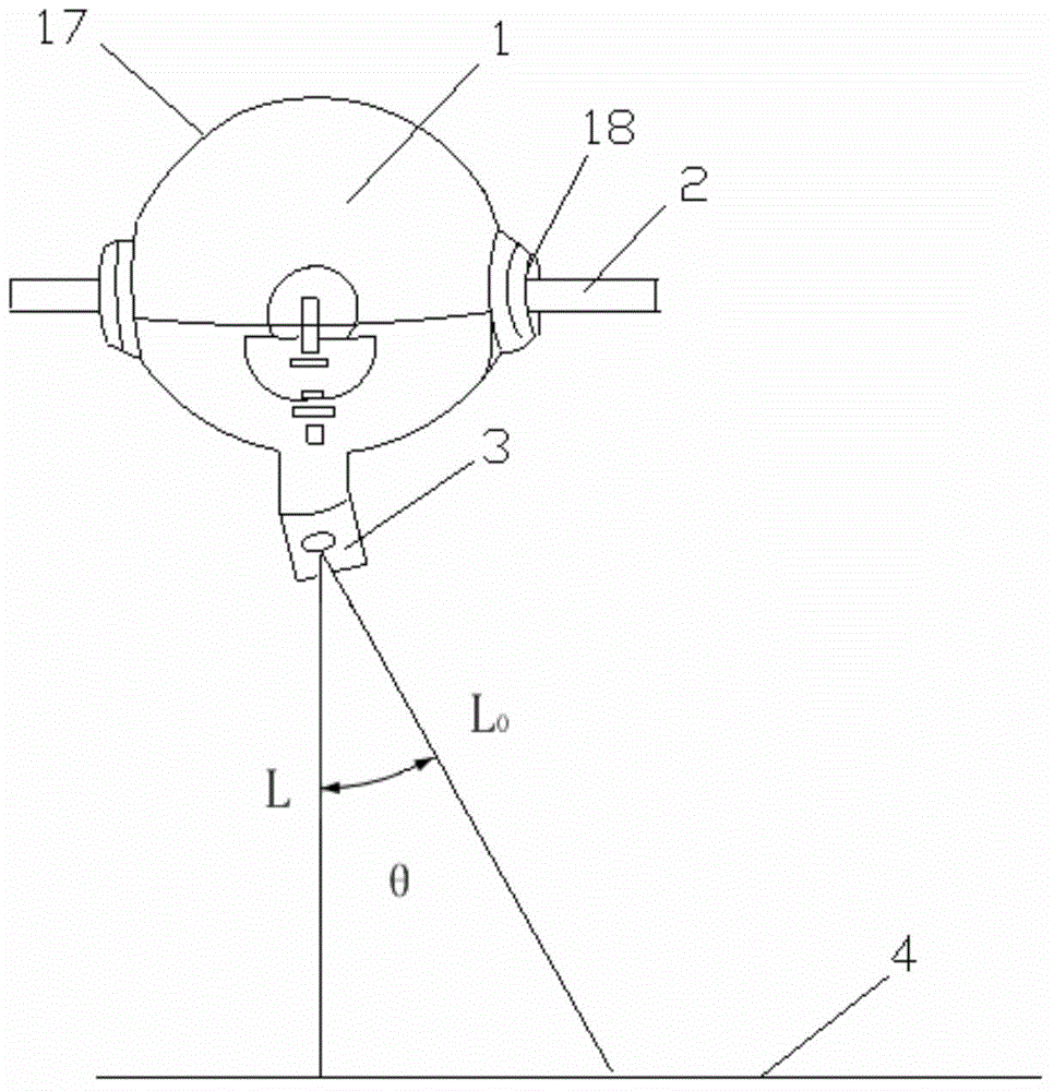
[0048] see Figure 1 to Figure 2. It should be noted that the structures, proportions, sizes, etc. shown in the drawings attached to this specification are only used to match the content disclosed in the specification, for those who are familiar with this technology to understand and read, and are not used to limit the implementation of the present invention. Limiting conditions, so there is no technical substantive meaning, any modification of structure, change of proportional relationship or adjustment of size, without affecting the effect and purpose of the present invention, should still fall within the scope of the present invention. The disclosed technical content must be within the scope covered. At the sam...


PUM


Abstract

The invention provides a conductor sag monitoring device based on laser distance measurement. The monitoring device comprises a laser distance measurement sensor hung on a conductor. The laser distance measurement sensor is used for measuring the distance between the conductor and the ground. The monitoring device can further comprise an angle sensor, the angle between a laser pulse and a perpendicular line perpendicular to the ground is measured through the angle sensor, and the perpendicular distance between the conductor and the ground is calculated. The invention further provides two methods for using the conductor sag monitoring device based on the laser distance measurement. The distance between the conductor and the ground and the conductor sag are measured with the laser distance measurement methods, the measurement accuracy is high, the implement methods are simple, and the collected data are accurate and reliable.

Description

technical field [0001] The invention relates to a wire sag monitoring device based on laser distance measurement. [0002] The invention also relates to two monitoring methods using a wire sag monitoring device based on laser distance measurement. Background technique [0003] Conductor sag refers to the vertical distance between the lowest point of the conductor and the line between the two suspension points when the suspension height of the conductors on two adjacent poles is the same on a flat ground; Similarly, at this time, there will be two sags within a span, that is, there are two vertical distances from the two suspension points of the wire to the lowest point of the wire, which are called the maximum sag and the minimum sag. The position where the maximum sag occurs depends on the specific circumstances, among which the common maximum sag of the wires between adjacent towers with a height difference of no more than 10% appears in the center of the span. From the ...

Claims


Application Information

Patent Timeline
IPC IPC(8): G01B11/02
Inventor 党朋赵文彬袁辉黄国飞
Owner SHANGHAI ELECTRIC CABLE RES INST
Why Eureka
Try Eureka