Mechanical connection structure for detecting dynamic torque by adopting static torque sensor

A technology of mechanical connection structure and static torque, which is applied in the direction of instruments, measuring devices, torque measurement, etc., can solve the problems of high cost of dynamic torque detection of motor shaft, inaccurate and stable detection data, complex structure of dynamic torque sensor, etc. Achieve the effect of simple structure, improved accuracy and stability, and stable performance

Active Publication Date: 2015-03-25
韩亚兰
View PDF6 Cites 9 Cited by
  • Summary
  • Abstract
  • Description
  • Claims
  • Application Information

AI Technical Summary

Problems solved by technology

It is precisely because of the rotational movement between the resistance strain sensing device on the shaft of the dynamic torque sensor and the power supply and signal output device outside the shaft, which results in the performance of power supply to the resistance strain sensing device and the transmission of torque sensing signals to the outside of the shaft. It is not stable enough, resulting in relatively large differences in the detected torque data in different time periods under the same detection conditions, resulting in inaccurate and stable detection data; the second is due to the need to supply power and The torque sensing signal is transmitted outside the shaft, so that the maximum speed of the dynamic torque sensor shaft is limited, that is, the dynamic torque sensor can only be used for dynamic torque detection of motor shafts with low speeds, and cannot be used for dynamic torque detection of motor shafts with higher speeds. Torque detection; third, the structure of the dynamic torque sensor is complex and the price is high, resulting in high cost of dynamic torque detection of the motor shaft

Method used


Image

  • Mechanical connection structure for detecting dynamic torque by adopting static torque sensor
  • Mechanical connection structure for detecting dynamic torque by adopting static torque sensor
  • Mechanical connection structure for detecting dynamic torque by adopting static torque sensor

Examples


Embodiment 1

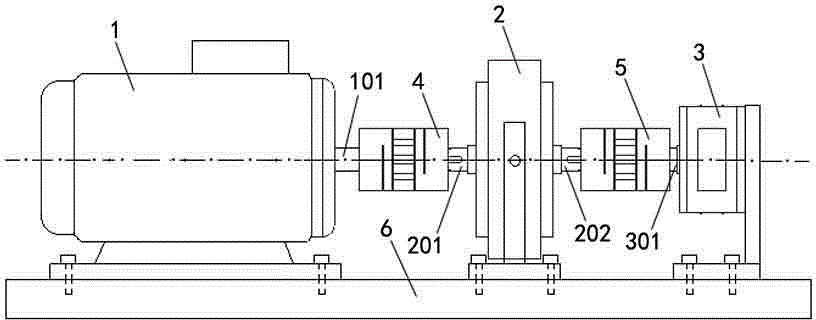
[0022] See figure 2 , the motor 1 to be detected, the magnetic powder clutch 2 and the static torque sensor 3 are installed coaxially on a metal platform 6 through couplings 4 and 5 . The coupling 4 coaxially connects the drive shaft 201 of the magnetic powder clutch 2 with the rotating shaft 101 of the motor 1 , and the coupling 5 coaxially connects the driven shaft 202 of the magnetic powder clutch 2 with the detection shaft 301 of the static torque sensor 4 . Then the magnetic powder clutch 2 is connected with the power supply, and the torque digital display instrument is connected with the power supply and the static torque sensor 3 . Turn on the power supply of the motor 1 to start the motor 1, adjust the working current of the magnetic powder clutch 2, and this current makes the friction disc fixed together with the driven shaft 202 inside the magnetic powder clutch 2 and the friction disc fixed together with the drive shaft 201 to generate Mechanical friction coupling...

Embodiment 2

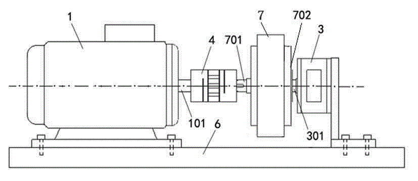
[0024] See image 3 , similar to Embodiment 1, the difference is that the motor 1 to be tested, the magnetic powder brake 7 and the static torque sensor 3 are installed coaxially on a metal platform 6 through a coupling 4 . That is, the rotating shaft 701 of the magnetic powder brake 7 is connected to the rotating shaft 101 of the motor 1 through the coupling 4 . The rear casing 702 of the magnetic powder brake 7 opposite to the rotating shaft 701 is coupled with the detection shaft 301 of the static torque sensor 3 . Then the magnetic powder brake 7 is connected with the power supply, and the torque digital display instrument is connected with the power supply and the static torque sensor 3 . Turn on the power supply of the motor 1 to start the motor 1, adjust the working current of the magnetic powder brake 7, this current makes the friction disc fixed together with the 7 rotating shaft 701 inside the magnetic powder brake and the friction plate fixed together with the rear...


PUM


Abstract

A mechanical connection structure for detecting dynamic torque by adopting a static torque sensor comprises a detected motor, a rotating shaft load regulator and the static torque sensor. The rotating shaft load regulator is installed between the motor and the static torque sensor, and the rotating shaft load regulator, the motor and the static torque sensor are coaxially connected. The mechanical connection structure has the advantages that as a detection shaft of the static torque sensor does not rotate and only twists and deforms, the mechanical connection structure is simple, mature in technology and stable in performance, and the static torque sensor is superior to a dynamic torque sensor of the same grade and the same specification in accuracy and performance stability; accordingly, the accuracy and stability of data detection are improved by adopting the static torque sensor; the rotating speed, detected by the static torque sensor, of the motor is higher than the rotating speed, detected by the dynamic torque sensor, of the motor, and therefore the applicable rotating speed range of the mechanical connection structure is larger; because the price of the static torque sensor is far lower than that of the dynamic torque sensor, the cost for detecting the dynamic torque of the motor or other rotating shaft power machines is lowered.

Description

technical field [0001] The invention relates to the technical field of mechanical torque detection of a rotating shaft, and relates to a mechanical connection structure that uses a static torque sensor to detect dynamic torque. Background technique [0002] See figure 1 , the dynamic torque detection of the motor, including the motor 1 under test, the dynamic torque sensor 2, and the magnetic powder clutch 3. The motor 1 under test is coaxially connected with the dynamic torque sensor 2 and the magnetic powder brake 3 with a shaft coupling. The rotating shaft of the motor 1 drives the dynamic torque sensor 2 and the shaft of the magnetic powder clutch 3 to rotate together, adjusts the working current of the magnetic powder brake 3, and applies a resistance torque to the rotating shaft of the motor 1, and the dynamic torque sensor 2 directly connected with the motor 1 coaxially outputs dynamic torque. The torque detection data is given to the torque display instrument, and ...

Claims


Application Information

Patent Timeline
Patent Type & Authority Applications(China)
IPC IPC(8): G01L3/22
Inventor 韩亚兰
Owner 韩亚兰
Why Eureka
Try Eureka