
Method of reducing short channel effect of mos transistor

A MOS transistor, short-channel effect technology, applied in the fields of semiconductor devices, semiconductor/solid-state device manufacturing, electrical components, etc., can solve the problems of short-channel effect, process control difficulty, etc. The effect of channeling

Active Publication Date: 2018-03-06
SEMICON MFG INT (SHANGHAI) CORP
View PDF6 Cites 0 Cited by
  • Summary
  • Abstract
  • Description
  • Claims
  • Application Information

AI Technical Summary

Problems solved by technology

[0004] More specifically, in the prior art, an important problem is that impurities in the source and drain regions will diffuse laterally during the annealing process, and this lateral diffusion will become more and more serious as the gate feature size continues to shrink. The short channel effect (SCE); especially when SiGe or SiC is used as the source and drain region, since this source and drain region is generally produced by the epitaxial process, the corresponding source and drain region III-V will be in-situ epitaxially doped at the same time Group impurities, this kind of in-situ epitaxial doping has a more serious short channel effect due to the difficulty of process control

Method used


Image

  • Method of reducing short channel effect of mos transistor
  • Method of reducing short channel effect of mos transistor
  • Method of reducing short channel effect of mos transistor

Examples


Embodiment Construction

[0020] In order to make the content of the present invention clearer and easier to understand, the content of the present invention will be described in detail below in conjunction with specific embodiments and accompanying drawings.

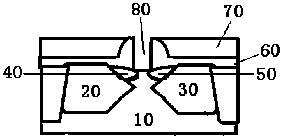
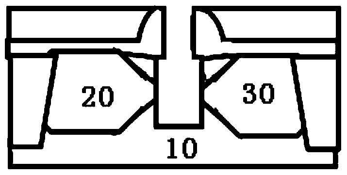
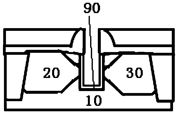
[0021] Figure 1 to Figure 6 Each step of the method for reducing the short channel effect of a MOS transistor according to a preferred embodiment of the present invention is schematically shown.

[0022] Specifically, as Figure 1 to Figure 6 As shown, the method for reducing the short channel effect of a MOS transistor according to a preferred embodiment of the present invention includes:

[0023] Such as figure 1 As shown, a triangular source 20 and a triangular drain 30 are formed in the well 10 of the silicon wafer, wherein one corner of the triangular source 20 is opposite to one corner of the triangular drain 30 , and in the triangular source 20 and the triangular drain 30 A lightly doped source region 40 and a lightly doped drain regio...


PUM


Abstract

A method for lowering MOS transistor short-channel effect comprises the steps that a triangular source electrode and a triangular drain electrode are formed in a trap of a silicon wafer, wherein one angle of the triangular source electrode and one angle of the triangular drain electrode are opposite, a light dope source zone and a light dope drain zone are formed at the opposite angles respectively, a first dielectric layer and a second dielectric layer are formed on the silicon wafer in sequence, and gate grooves are formed in the first dielectric layer and the second dielectric layer; the gate grooves enter the trap; silicon nitride layers are formed on parts of the side walls of the gate grooves, so that silicon nitride layers are formed on the surfaces of the triangular source electrode, the triangular drain electrode, the light dope source zone, the light dope drain zone and the trap; silicon is used for filling the gate grooves partially, so that silicon fills the parts, in a substrate, of the gate grooves; the first dielectric layer is subjected to wet etching, so that the size of the gate grooves which are not filled is increased, and accordingly expanded gate grooves are formed; and the expanded gate grooves are filled with gate materials.

Description

technical field [0001] The invention relates to the field of semiconductor manufacturing, more specifically, the invention relates to a method for reducing the short channel effect of a MOS transistor. Background technique [0002] Metal-oxide-semiconductor (Metal-Oxide-Semiconductor) transistors are referred to as MOS transistors for short. Nowadays, MOS transistors have been widely used in most digital circuits and some analog circuits. [0003] However, as the device size shrinks, short-channel effects will appear, thereby affecting device performance. Specifically, when the channel length of the MOS transistor is shortened to be comparable to the sum of the width of the source and drain depletion layers, the device will deviate from the behavior of the long channel, and the channel edges (such as the source, drain and insulation The perturbation of the area edge) will become more important. Therefore, the characteristics of the device will no longer obey the assumption...

Claims


Application Information

Patent Timeline
Patent Type & Authority Patents(China)
IPC IPC(8): H01L21/336
CPCH01L29/66409
Inventor 赵猛
Owner SEMICON MFG INT (SHANGHAI) CORP
Learn More