High-load inverter

An inverter and high-load technology, applied in the field of electronics, can solve the problem of low load capacity of the inverter, and achieve the effects of simple structure, improved load capacity and energy saving

Inactive Publication Date: 2015-03-25
CHENGDU CHUANGTU TECH
View PDF0 Cites 1 Cited by
  • Summary
  • Abstract
  • Description
  • Claims
  • Application Information

AI Technical Summary

Problems solved by technology

[0004] The purpose of the present invention is to overcome the defect that the load capacity of current inverters is not high, and provide a high-load inverter that can meet the needs of high-power electrical appliances

Method used


Image

  • High-load inverter

Examples


Embodiment

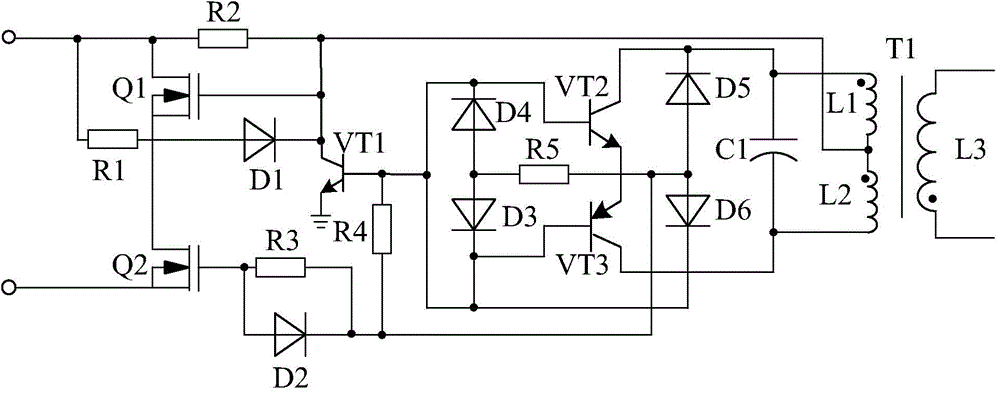
[0014] like figure 1 As shown, the high-load inverter of the present invention is composed of a transformer T1, an inverter circuit, a logic control circuit connected to the inverter circuit, and a filter circuit connected to the logic control circuit. The filter circuit and the primary side of the transformer T1 connected.

[0015] Among them, the inverter circuit consists of field effect transistor Q1, field effect transistor Q2, triode VT1, a resistor R2 connected to the drain of field effect transistor Q1 at one end and connected to the collector of triode VT1 at the other end, and the P pole is passed through resistor R1 Diode D1 connected to the drain of the field effect transistor Q1, N pole connected to the collector of the triode VT1, P pole connected to the gate of the field effect transistor Q2, N pole connected to the base of the triode VT1 through the resistor R4 A diode D2 connected to the pole, and a resistor R3 connected in parallel with the diode D2; the drai...


PUM


Abstract

The invention discloses a high-load inverter. The high-load inverter is characterized by being composed of a transformer T1, an inverter circuit, a logic control circuit connected with the inverter circuit, and a filter circuit connected with the logic control circuit, and the filter circuit is connected with the primary side of the transformer T1; the inverter circuit is composed of a field-effect transistor Q1, a field-effect transistor Q2, a triode VT1, a resistor R2, a diode D1, a diode D2 and the like, wherein one end of the resistor R2 is connected with the drain electrode of the field-effect transistor Q1, the other end of the resistor R2 is connected with the collector electrode of the triode VT1, the P electrode of the diode D1 passes through a resistor R1 and then is connected with the drain electrode of the field-effect transistor Q1, the N electrode of the diode D1 is connected with the collector electrode of the triode VT1, the P electrode of the diode D2 is connected with the grid electrode of the field-effect transistor Q2, and the N electrode of the diode D2 passes through a resistor R4 and then is connected with the base electrode of the diode VT1. The load capacity of the inverter is greatly improved, and the requirements for using high-power electric appliances or multipurpose electric appliances at the same time can be met.

Description

technical field [0001] The invention relates to the field of electronics, in particular to a high-load inverter. Background technique [0002] Inverters convert DC power into AC power. It is widely used in air conditioners, home theaters, electric grinding wheels, electric tools, sewing machines, DVD, VCD, computers, TVs, washing machines, range hoods, refrigerators, VCRs, massagers, fans, lighting, etc. In foreign countries, due to the high penetration rate of automobiles, the inverter can be used to connect the battery to drive electrical appliances and various tools to work when going out to work or travel. Connect household appliances to the output of the power converter to use various appliances in the car. [0003] However, the load capacity of the current inverter is not high, and it is difficult to meet the needs of some high-power electrical appliances. Contents of the invention [0004] The purpose of the present invention is to overcome the defect of low load...

Claims


Application Information

Patent Timeline
Patent Type & Authority Applications(China)
IPC IPC(8): H02M7/537
CPCH02M7/537
Inventor 周鹏程刘芳
Owner CHENGDU CHUANGTU TECH
Why Eureka
Try Eureka