motor control unit

A control device and motor technology, applied in motor control, motor generator control, AC motor control, etc., can solve problems such as non-optimal state, and achieve the effect of extensive minor abnormalities

Active Publication Date: 2018-03-13
DENSO CORP
View PDF9 Cites 0 Cited by
  • Summary
  • Abstract
  • Description
  • Claims
  • Application Information

AI Technical Summary

Problems solved by technology

In such cases, this may not be the preferred state due to differences in the radiated performance of the two power inverter circuitry

Method used


Image

  • motor control unit
  • motor control unit
  • motor control unit

Examples


no. 1 example

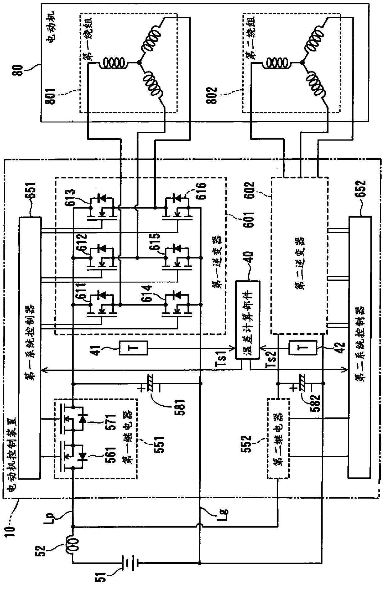
[0025] The following will refer to Figure 1 to Figure 7 A motor control device according to a first embodiment of the present disclosure is explained.

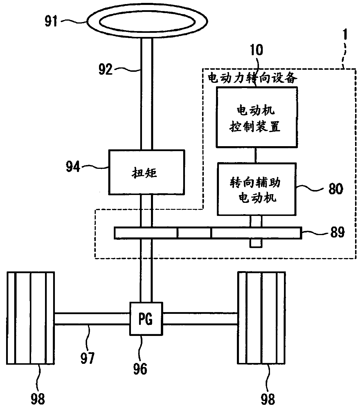
[0026] figure 2 is the overall configuration of the steering system 90 provided with the electric power steering apparatus 1 . A torque sensor 94 that detects steering torque is disposed in a steering shaft 92 connected to a steering wheel 91 . The steering shaft 92 has a pinion 96 at the end of the steering shaft 92 . The pinion gear 96 meshes with the rack shaft 97 . A pair of wheels 98 are rotatably connected to both ends of the rack shaft 97 via connecting rods or the like. The rotation of the steering shaft 92 is converted into linear motion of the rack shaft 97 by the pinion 96 . The pair of wheels 98 is steered at an angle displaced by the linear motion of the rack shaft 97 .

[0027] The electric power steering apparatus 1 includes a reduction gear 89 that slows down the rotation of an output shaft of the motor...

no. 2 example

[0079] The following will refer to Figure 8 flow chart and Figure 9 The schema table describes the second embodiment of the present disclosure. The second embodiment is about the circuit configuration (refer to figure 1 and Figure 5 ) have basically the same configuration. The second embodiment executes from the temperature difference monitoring process in the first embodiment (refer to Figure 6 ) for further processing to be applied.

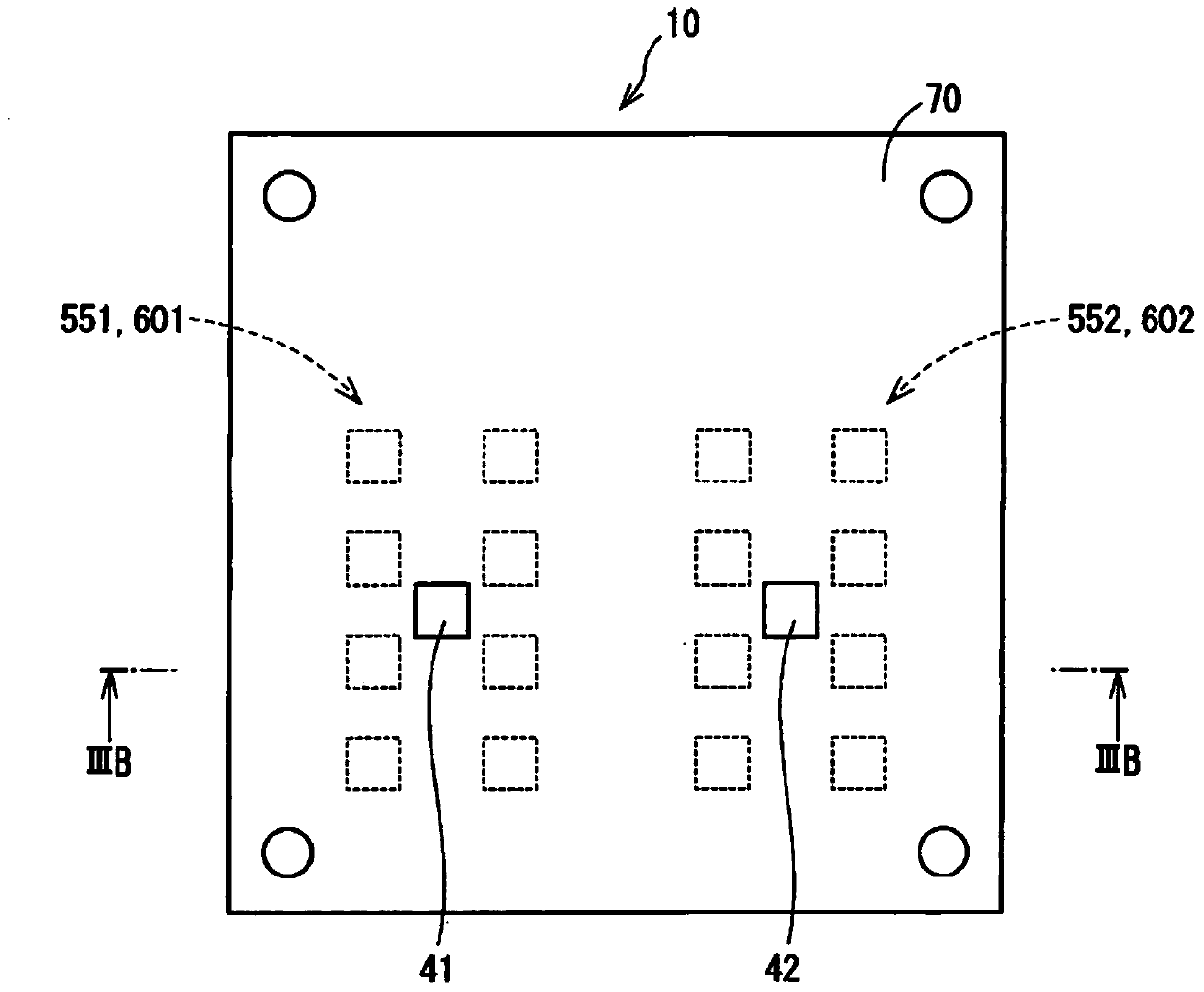
[0080] exist Figure 8 In S31 of , the temperature difference calculation component 40 acquires the sensor value Ts1 of the first temperature sensor 41 and the sensor value Ts2 of the second temperature sensor 42 . Initially, the sensor values ​​Ts1, Ts2 are compared with the temperature threshold Tz. The temperature threshold Tz is set to a temperature value which is considered to absolutely represent an abnormality in the heat generation of the conversion elements in the inverters 601, 602. That is, when the sensor value of one of...


PUM


Abstract

A motor control device is provided which controls the drive of a motor (80) having two pairs of winding sets (801, 802). The motor control device includes a current command value calculation unit (15), a first system, a second system, and a temperature difference calculation unit (40). The first system includes a first power inverter circuit (601), a first temperature sensor (41), a first current limit setting component (201), and a first controller (651). The second system includes a second power inverter circuit (602), a second temperature sensor (42), a second current limit setting component (202), and a second controller (652). One of the first controller (651) and the second controller (652) stops driving of one of the first power inverter circuit (601) and the second power inverter circuit (602) or lowers its current limit value.

Description

technical field [0001] The present disclosure relates to a motor control device that controls driving of a motor. Background technique [0002] Patent Document 1: JP-A-2003-153588 [0003] A general motor control device controls the driving of a motor having a plurality of winding sets with a plurality of power inverter circuits. In addition, the device has a temperature sensor to detect the temperature of a power conversion element receiving a large current, and the temperature sensor is placed near the power inverter circuit. The device monitors abnormal heat generation in power conversion components. [0004] For example, in the motor drive device described in Patent Document 1, temperature sensors placed in or near the power modules of the two inverter circuits detect the temperatures of the power modules, respectively. When the temperature expressed in thermal value of one of the power modules exceeds a temperature threshold, the inverter circuit connected to the ele...

Claims


Application Information

Patent Timeline
Patent Type & Authority Patents(China)
IPC IPC(8): H02P27/06H02P29/00H02P6/06H02P6/08H02P6/12H02P6/28H02P21/00H02P21/22H02P21/36H02P25/02H02P25/22H02P29/68
CPCH02P21/00H02P21/14B62D5/0403B62D5/0484B62D5/0496H02P21/22H02P29/032H02P29/68B62D5/0463H02P25/22H02P27/06H02M1/32H02M7/219
Inventor 原芳道
Owner DENSO CORP
Why Eureka
Try Eureka