Repeater and information transmission method and communication module hardware ID identification method of repeater

A technology of communication modules and repeaters, which is applied in signal transmission systems, transmission systems, instruments, etc., can solve problems such as increased labor costs, lack of functions, and low performance, so as to ensure reliability and stability and extend communication relay The effect of distance, convenient installation and use

Active Publication Date: 2015-03-25
WILLFAR INFORMATION TECH CO LTD
View PDF5 Cites 9 Cited by
  • Summary
  • Abstract
  • Description
  • Claims
  • Application Information

AI Technical Summary

Problems solved by technology

The disadvantage of this communication scheme is that if the installation location of the terminal is in the mobile signal blind area or the signal quality is not ideal, the terminal and the main station cannot communicate or the communication success rate is not high
[0005] 1. It only supports terminals and communication modules designed and produced by itself, and cannot be compatible with terminals and communication modules of other manufacturers. If customers use communication repeaters from multiple manufacturers at the same time, it will be inconvenient to manage and maintain, and it will also increase manpower and other costs.
[0006] 2. The existing communication repeater can basically only complete the transmission of communication data and a small amount of control signals. Due to the limited number of communication cables, the terminal cannot reset the communication module, power off and serial port hardware flow after using the existing repeater. Control, communication module hardware ID identification and other controls, unable to realize communication module control and two-way transmission of status signals, resulting in loss of function

Method used


Image

  • Repeater and information transmission method and communication module hardware ID identification method of repeater
  • Repeater and information transmission method and communication module hardware ID identification method of repeater
  • Repeater and information transmission method and communication module hardware ID identification method of repeater

Examples


Embodiment Construction

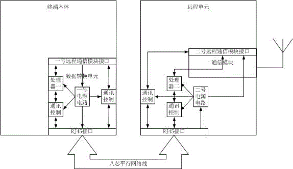
[0059] like figure 1 As shown, the present invention includes a data conversion unit and a remote unit. The communication module on the original power consumption information collection terminal is installed on the remote unit; the remote unit is also provided with an antenna, and the communication module is connected with the antenna to perform wireless communication. The data conversion unit used to virtualize the communication module is installed on the original power consumption information collection terminal, and the data conversion unit and the remote unit are connected by wires.

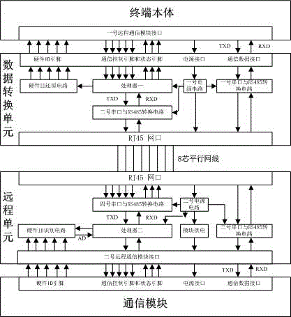
[0060] like figure 2 As shown, the data conversion unit of the present invention includes a hardware ID restoration circuit, a processor one, a No. 1 serial port and RS485 conversion circuit, a No. 2 serial port and RS485 conversion circuit, and a No. 1 power supply circuit. One end of the hardware ID recovery circuit is connected to the No. 1 remote communication module interface of the t...


PUM


Abstract

The invention discloses a repeater and an information transmission method and a communication module hardware ID identification method of the repeater. The repeater comprises a terminal and a communication module installed on the terminal. The repeater further comprises a data conversion unit and a remote unit, the communication module originally installed on the terminal is installed on the remote unit, the remote unit is further provided with an antenna and can be connected with the communication module for wireless communication, the data conversion unit used for virtualizing the communication module is installed on the terminal and is connected with the terminal through a remote communication module interface, and the data conversion unit is in wired connection with the remote unit. The repeater achieves cross-specification, cross-manufacturer and cross-product compatibility; the communication module can be installed at the position with good signal intensity, the communication distance between the terminal and the communication module is effectively prolonged, and the communication effect is excellent. The repeater dispenses with an external power source, can work normally by only getting electricity from the terminal and is convenient to install and use.

Description

technical field [0001] The invention relates to a repeater, its information transmission method and a communication module hardware ID identification method. Background technique [0002] The current uplink communication method commonly used in the power consumption information collection system is: the communication module is installed on the power consumption information collection terminal (hereinafter referred to as the terminal), and the terminal communicates with the main station of the power consumption information collection system (hereinafter referred to as the main station) through the communication module. The disadvantage of this communication scheme is that if the installation location of the terminal is in a mobile signal blind area or the signal quality is not ideal, the terminal cannot communicate with the main station or the communication success rate is not high. [0003] In order to solve the problem of low data acquisition success rate due to unsatisfact...

Claims


Application Information

Patent Timeline
Patent Type & Authority Applications(China)
IPC IPC(8): H04B1/40G08C17/02
Inventor 范律孙煦王锋刘连义
Owner WILLFAR INFORMATION TECH CO LTD
Why Eureka
Try Eureka