System for testing influences of microvibration on imaging quality of long-focus camera

A camera imaging and testing system technology, applied in image communication, television, electrical components, etc., can solve problems such as system-level full-link micro-vibration testing and evaluation, small instantaneous field of view, and reduced camera imaging quality.

Inactive Publication Date: 2015-03-25
CHANGCHUN INST OF OPTICS FINE MECHANICS & PHYSICS CHINESE ACAD OF SCI
View PDF6 Cites 12 Cited by
  • Summary
  • Abstract
  • Description
  • Claims
  • Application Information

AI Technical Summary

Problems solved by technology

However, due to the small instantaneous field of view of the long focal length camera, it is sensitive to external environmental interference, especially the moving parts and flexible parts on the installation platform will produce some tiny vibrations with small amplitude and high frequency when they are working. The camera optical components and camera structure cause the shake of the optical axis of the camera with a long focal length

Method used


Image

  • System for testing influences of microvibration on imaging quality of long-focus camera

Examples


Embodiment Construction

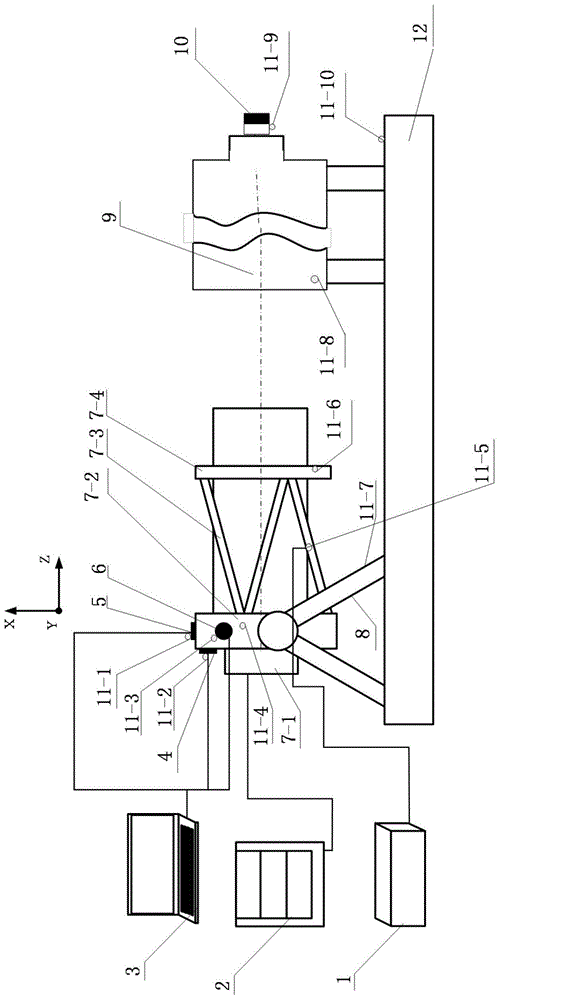
[0015] The present invention will be described in further detail below in conjunction with the accompanying drawings.

[0016] Such as figure 1 As shown, the test system for the influence of micro-vibration on the imaging quality of a long-focus camera, wherein the long-focus camera 7 is the camera to be tested, which includes camera electronics 7-1, camera main bearing plate 7-2, camera truss 7-3 and The camera secondary mirror mounting frame 7-4, the camera secondary mirror mounting frame 7-4 is installed on the camera truss 7-3, the camera truss 7-3 is installed on the camera main bearing plate 7-2, and the camera electronics 7-1 also Installed on the main bearing plate 7-2 of the camera. The long focal length collimator 9 and the knife-edge target 10 are simulated targets. The Z direction reaction flywheel 4, the X direction reaction flywheel 5 and the Y direction reaction flywheel 6 follow the three orthogonal directions of XYZ (wherein the Z direction represents the di...


PUM


Abstract

The invention provides a system for accurately measuring and evaluating influences of microvibration on the imaging quality of a camera and belongs to the field of optical imaging. A dynamic signal acquisition instrument is connected with ten three-way acceleration sensors; a graphic workstation is connected with a camera imaging electronic part; a counteractive flywheel controller is connected with a Z-direction counteractive flywheel, an X-direction counteractive flywheel and a Y-direction counteractive flywheel through cables; the Z-direction counteractive flywheel, the X-direction counteractive flywheel and the Y-direction counteractive flywheel are installed on a camera main force bearing plate, the long-focus camera is installed on a camera support, the camera support and a long-focus collimator are horizontally disposed on a vibration isolation air floating platform, the optical axis of the long-focus camera coincides with the optical axis of the long-focus collimator by adjusting side swaying and pitching of the camera support, and a knife edge target is placed at the focus of the long-focus collimator; the ten three-way acceleration sensors adhere to the X-direction counteractive flywheel, the Z-direction counteractive flywheel, the Y-direction counteractive flywheel, the camera main force bearing plate, a camera truss, a camera secondary mirror mounting rack, the camera support, the long-focus collimator, the knife edge target and the large vibration isolation air floating platform.

Description

technical field [0001] The invention relates to a test system capable of testing and evaluating the influence of micro-vibration on the imaging quality of a long-focus camera, and belongs to the field of optical imaging. Background technique [0002] Long focal length cameras are widely used in ground-based, space-based and space-based platforms due to their high angular resolution and the ability to obtain clear images of distant targets. However, due to the small instantaneous field of view of the long focal length camera, it is sensitive to external environmental interference, especially the moving parts and flexible parts on the installation platform will produce some tiny vibrations with small amplitude and high frequency when they are working. The optical components of the camera and the structure of the camera cause the optical axis of the camera with a long focal length to shake during the exposure or integration time, causing blurring of the optical image and reduci...

Claims


Application Information

Patent Timeline
IPC IPC(8): H04N17/00
Inventor 金光安源钟兴张雷范国伟张元孔令胜谢晓光冯汝鹏杨飞贾学志徐开陶淑苹
Owner CHANGCHUN INST OF OPTICS FINE MECHANICS & PHYSICS CHINESE ACAD OF SCI
Why Eureka
Try Eureka