Eureka AIR delivers breakthrough ideas for toughest innovation challenges, trusted by R&D personnel around the world.

Multipart insulating element, in particular for a fuel injection device

A technology for a fuel injection device and an isolating element, which is applied in the directions of a fuel injection device, a special fuel injection device, a fuel injection device with noise reduction measures, etc. Stress reduction, improved noise damping, reduced deflection effects

Active Publication Date: 2015-03-25
ROBERT BOSCH GMBH
View PDF10 Cites 3 Cited by
  • Summary
  • Abstract
  • Description
  • Claims
  • Application Information

AI Technical Summary

Problems solved by technology

However, this type of noise damping is very complex, difficult to assemble and expensive

Method used


Image

  • Multipart insulating element, in particular for a fuel injection device
  • Multipart insulating element, in particular for a fuel injection device
  • Multipart insulating element, in particular for a fuel injection device

Examples


Embodiment Construction

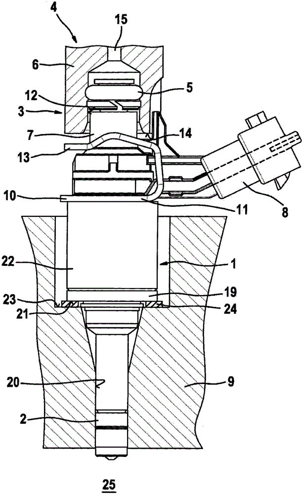
[0020] In order to understand the present invention, next by means of figure 1 Known embodiments of fuel injection systems are described in more detail. figure 1 An exemplary embodiment of a valve in the form of an injection valve 1 for a fuel injection system of a hybrid compression external ignition internal combustion engine is shown in side view. The fuel injection valve 1 is part of a fuel injection system. The fuel injector 1 , which is designed as a direct injection valve for injecting fuel directly into the combustion chamber 25 of the internal combustion engine, is inserted with its downstream end into the receiving bore 20 of the cylinder head 9 . Sealing ring 2 (especially made of Teflon constituted) for optimal sealing of the fuel injector 1 against the wall of the receiving bore 20 of the cylinder head 9 .

[0021] A flat intermediate element 24 is inserted between the shoulder 21 of the valve housing 22 and the projection 23 of the receiving opening 20 , whic...


PUM


Abstract

The invention relates to an insulating element for a fuel injection device. The insulating element is characterized particularly by the implementation of a low-noise design. The fuel injection device comprises at least one fuel injection valve (1), a receiving bore (20) in a cylinder head (9) for the fuel injection valve (1), and the insulating element (30) between a valve housing (22) of the fuel injection valve (1) and a wall of the receiving bore (20). The insulating element (30) has an inner insulating ring (33) which is encapsulated between an outer ring (31) and an inner ring (32). The outer ring (31) is oriented towards the fuel injection valve (1), and the inner ring (32) is oriented towards the wall of the receiving bore (20) such that the outer ring (31) rests on the fuel injection valve (1) and the inner ring (32) rests on the cylinder head (9) in the assembled state of the insulating element (30). The fuel injection device is particularly suitable for directly injecting fuel into a combustion chamber of a mixture-compressing internal combustion engine with an externally supplied ignition.

Description

technical field [0001] The invention relates to a multi-part spacer element, in particular for a fuel injection device, according to the generics of the independent claims. Background technique [0002] exist figure 1 shows an example of a fuel injection device known from the prior art, in which a flat intermediate element is arranged on a fuel injection valve mounted in a receiving bore of a cylinder head of an internal combustion engine. Such an intermediate element is placed in the known manner as a support element in the form of a washer on the boss of the receiving bore of the cylinder head. Manufacturing and assembly tolerances are compensated for by means of such an intermediate element and support without lateral forces is ensured even in the event of a slightly inclined position of the fuel injection valve. The fuel injection device is particularly suitable for use in fuel injection systems for hybrid compression externally ignited internal combustion engines. ...

Claims


Application Information

Patent Timeline
Patent Type & Authority Applications(China)
IPC IPC(8): F02M61/14
CPCF02M2200/858F02M2200/9023F02M2200/03F02M2200/9053F02M2200/306F02M61/14F02M2200/09
Inventor M·科哈诺夫斯基J·克雷默M·舍费尔T·弗勒纳M·弗里德里希
Owner ROBERT BOSCH GMBH
Why Eureka
Eureka Blog
Learn More