

Stirring tank
A mixing tank and agitator technology, applied to mixer accessories, mixers with rotating agitating devices, dissolving, etc., can solve problems such as uneven heating or cooling of materials, unqualified products, unfavorable chemical and chemical processes, etc., to achieve improvement The effect of quality and uniform heat transfer
- Summary
- Abstract
- Description
- Claims
- Application Information
AI Technical Summary
Problems solved by technology
Method used
Image

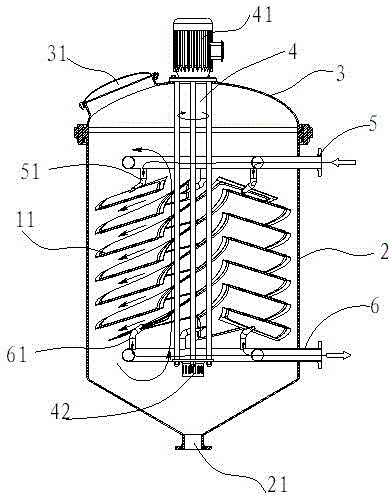
Examples
Embodiment 2
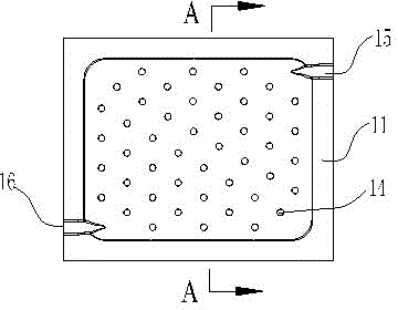
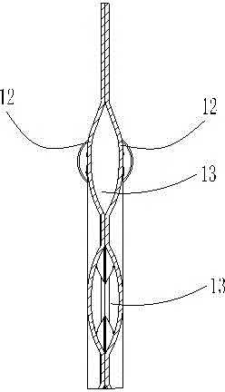
[0029] The difference from Example 1 is that, as Figure 4 and Figure 5 As shown, the structure of the hollow cavity 103 of the spiral heat exchange plate 101 is different from the structure of the hollow cavity in Example 1, and the spiral heat exchange plate 101 in Example 2 includes two stacked heat exchange The heat plate 102 is provided with a hollow cavity 103 after the two heat exchange plates 102 are stacked, and the hollow cavity 103 is as Figure 5 As shown, the welds of the two heat exchange plates 102 are welded into an S shape, so that the hollow cavity 103 of the heat exchange plate 101 is also set as an S-shaped flow channel, and the hollow cavity 103, the fluid inlet header 5 and the The fluid outlet header 6 forms a connected cavity, and the heat exchange plate 101 is arranged in a spiral shape. The fluid flows from the fluid inlet header 5 into the hollow cavity 103, and then flows out from the fluid outlet header 6. The S-shaped flow channel The contact a...
PUM
 Abstract
Description
Claims
Application Information