High-speed conveying system of high-speed precise paper cutting machine

A technology of conveying system and paper cutting machine, which is applied in the direction of sending objects, transportation and packaging, thin material processing, etc., which can solve the problems of high cost and maintenance cost, high operating noise, and low uniformity of cutting edges, so as to ensure safety Conveying, reducing manufacturing cost, and saving conveying space

Active Publication Date: 2015-04-01
中轻长泰(长沙)智能科技股份有限公司
View PDF7 Cites 5 Cited by
  • Summary
  • Abstract
  • Description
  • Claims
  • Application Information

AI Technical Summary

Problems solved by technology

The disadvantages of the existing paper cutters are that the cutting edges of paper and cardboard are generally not high in uniformity, and the squareness deviation is large. Automatic positioning adjustment, high operating noise, and can not complete the non-stop automatic stacking function, the production efficiency is relatively low
Existing paper cutters are generally only suitable for production with an annual output of less than 50,000 tons. However, most of the investment projects of large paper mills currently have an annual output of more than 200,000 tons. Simple paper cutters can no longer meet the production scale. requirements
Although the existing high-speed precision paper machines in the world have a high degree of automation and large production capacity, they are expensive in construction and maintenance

Method used


Image

  • High-speed conveying system of high-speed precise paper cutting machine
  • High-speed conveying system of high-speed precise paper cutting machine
  • High-speed conveying system of high-speed precise paper cutting machine

Examples


Embodiment Construction

[0029] Figure 1 to Figure 12 An embodiment of the invention is shown.

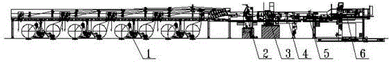
[0030] Such as figure 1 Shown: The high-speed precision paper cutter includes 1-unwinding frame system, 2-slitting system, 3-cross-cutting system, 4-high-speed conveying system, 5-folding system, 6-stacking system. 4- The role of the high-speed conveying system is to ensure that the paper web is conveyed smoothly during the production process and smoothly enters the stacking area in an accelerated manner.

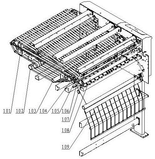
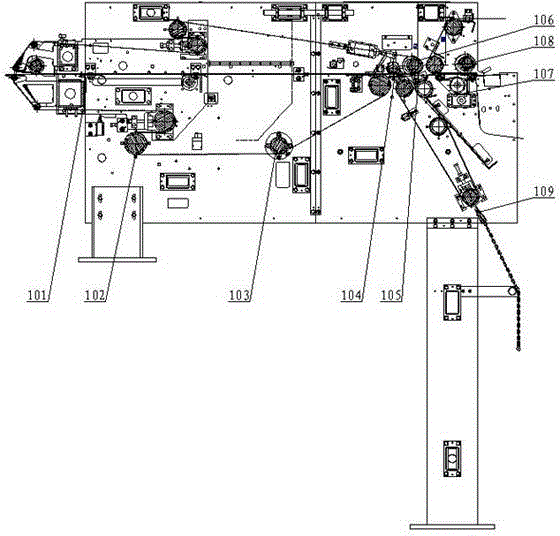
[0031] Such as figure 2 , image 3Shown: The high-speed conveying system of the high-speed precision paper machine includes 101-paper receiving trolley, 102-driving device, 103-tracting roller, 104-broken paper door device, 105-transporting platform, 106-regulating roller, 107-high-speed belt device , 108-pressure roller, 109-broken paper conveying device. When the cut paper web enters the 101-paper receiving trolley from the cross-cutting system, it will be clamped by the upper and lower belts o...


PUM


Abstract

The invention discloses a high-speed conveying system of a high-speed precise paper cutting machine. The high-speed conveying system comprises a paper receiving trolley, a broke door device, a broke conveying device, a conveying platform, a regulation roller, a high-speed belt device, a compression roller, a driving device, traction rollers and a whole rack, wherein the paper receiving trolley is positioned behind a transection system of the paper cutting machine and is installed between the left side plate and the right side plate of the whole rack; the broke door device is positioned behind the paper receiving trolley and is installed between the left side plate and the right side plate of the whole rack; the conveying platform is installed behind the broke door device; the broke conveying device is installed below the broke door device and the conveying platform; the regulation roller is arranged above the conveying platform; the high-speed belt device is positioned behind the conveying platform; the compression roller is tightly attached to the upper surface of the high-speed belt device; the driving device is positioned below the paper receiving trolley; a plurality of traction rollers are arranged and are installed between the left side plate and the right side plate of the whole rack through a mounted bearing. The high-speed conveying system has a tight structure, conveying space is greatly saved, manufacture cost is lowered, and paper webs with different thicknesses are guaranteed to be successfully conveyed.

Description

technical field [0001] The invention belongs to papermaking equipment, and relates to a high-speed conveying system of a high-speed precision paper cutting machine. Background technique [0002] Paper cutting machines are required for single-layer or multi-layer paper cutting in paper mills. The disadvantages of the existing paper cutters are that the cutting edges of paper and cardboard are generally not high in uniformity, and the squareness deviation is large. Automatic positioning adjustment, the operation noise is relatively large, and the function of automatic pallet change without stopping the machine cannot be completed, and the production efficiency is relatively low. Existing paper cutters are generally only suitable for production with an annual output of less than 50,000 tons. However, most of the investment projects of large paper mills currently have an annual output of more than 200,000 tons. Simple paper cutters can no longer meet the production scale. requ...

Claims


Application Information

Patent Timeline
Patent Type & Authority Applications(China)
IPC IPC(8): B65H29/16B65H29/12B65H29/60
Inventor 漆瑞王杰范海波翁嘉祥文雁
Owner 中轻长泰(长沙)智能科技股份有限公司
Why Eureka
Try Eureka