
Hydraulic lifting water-retaining wall

A kind of retaining wall and hydraulic technology, applied in the direction of coastline protection, jetty, bank pier, etc., can solve the problems of unfavorable people's hydrophilicity, near-water activities, affecting the viewing of river landscape, etc., to improve the effect of ecological beautification, significantly economical Practicality and simple construction

Inactive Publication Date: 2015-04-01
THE FRONTIER TECH RES INST OF TIANJIN UNIV
View PDF6 Cites 7 Cited by
  • Summary
  • Abstract
  • Description
  • Claims
  • Application Information

AI Technical Summary

Problems solved by technology

In order to protect the safety of people's lives and property, most rivers in my country have large flow, deep water and wide water surface under the design flood conditions, while in non-flood periods, the flow is small, the water is shallow and the water surface is narrow, and higher embankments and larger A height difference of several meters is formed between the low water surfaces, which seriously affects the viewing of the river landscape and is not conducive to the people's water-friendly and near-water activities.

Method used


Image

  • Hydraulic lifting water-retaining wall
  • Hydraulic lifting water-retaining wall
  • Hydraulic lifting water-retaining wall

Examples


Embodiment

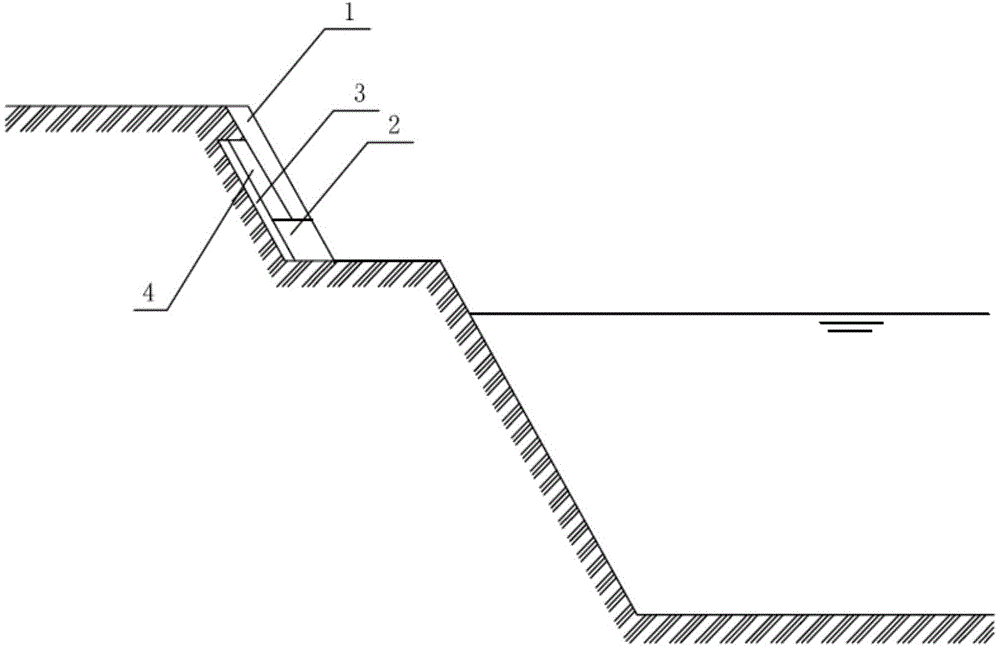
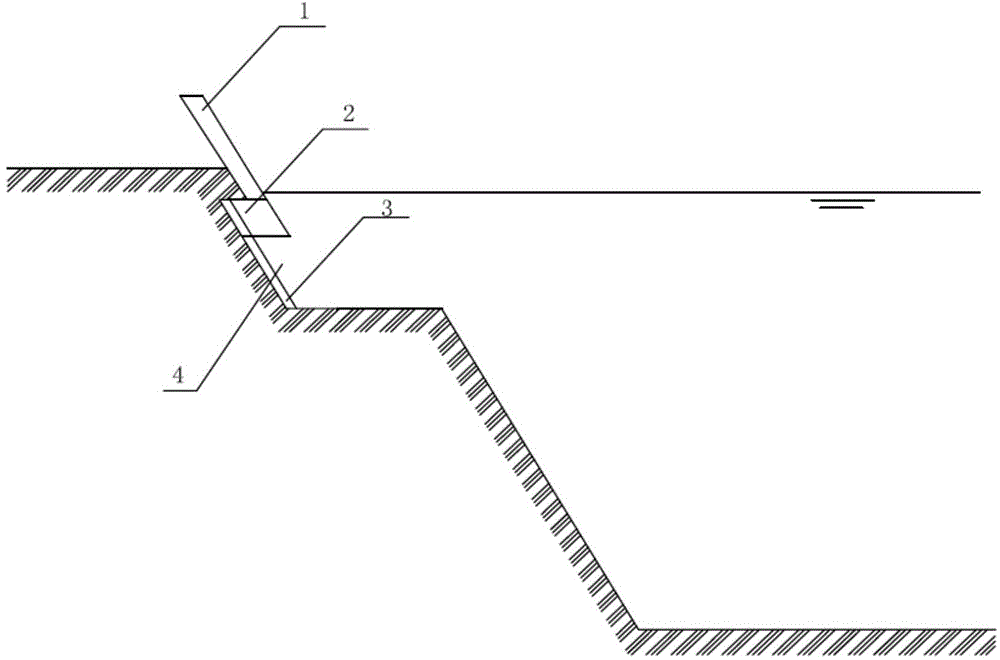
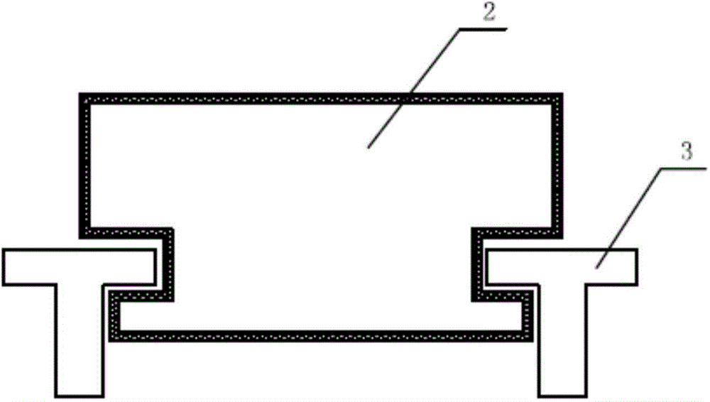
[0015] A hydraulic lifting retaining wall, such as Figure 1-3 As shown, it is set in the concrete reserved groove 4 of the embankment and is arranged in six sections, and is composed of a water-retaining steel plate 1 and a buoy box 2. The water-retaining steel plate 1 is a sandwich structure composed of two cuboid steel plates. Vertical reinforcing ribs are provided, and the back of the water-retaining steel plate 1 is fixed with a pontoon 2 with a parallelogram in cross section; the reserved concrete groove 4 is an inclined groove with a parallelogram in cross section, and the included angle between the inclined groove and the horizontal plane is 120°, and the concrete There are two T-shaped slide rails 3 in the middle of the reserved groove 4, the buoy box 2 is located in the middle of the two slide rails 3, the water retaining steel plate 1 is in natural contact with the top of the embankment, and the width of the buoy box 2 is the same as that of the concrete reserved gro...


PUM


Abstract

A hydraulic lifting water-retaining wall comprises a water-retaining steel plate and a floating box, wherein the water-retaining steel plate is of an interlayer structure formed by two rectangular solid steel plates, vertical reinforcement ribs are arranged between two layers of steel plates, and the floating box with a parallelogram shaped section is fixed on the back of the water-retaining steel plate; an inclined groove with a parallelogram shaped section is adopted as a concrete preformed groove, the included angle between the inclined groove and the level is 120 degrees, two T-shaped sliding rails are arranged in the middle of the concrete preformed groove, the floating box is arranged between the two sliding rails, the water-retaining steel is in natural contact with the top of a river levee, the width of the floating box is the same as that of the concrete preformed groove, and the floating box is lifted along the sliding rails in the concrete preformed groove. The hydraulic lifting water-retaining wall has the following advantages that when meeting flood, the water-retaining steel plate automatically lifts and plays the role of the water-retaining wall, and after flood, the water-retaining steel plate falls automatically to hide into the preformed groove in the inner side of the river levee to ensure safety of flood draining; the water-retaining wall is simple in structure and easy to implement, and has remarkable economical practicability.

Description

technical field [0001] The invention relates to a water retaining wall in a water conservancy project, in particular to a hydraulic lifting water retaining wall. Background technique [0002] In recent years, the demand for comprehensive improvement of rivers for the purpose of water environment and water ecological protection, as well as landscape and recreational environment creation has been increasing. In order to protect the safety of people's lives and property, most rivers in my country have large flow, deep water and wide water surface under the design flood conditions, while in non-flood periods, the flow is small, the water is shallow and the water surface is narrow, and higher embankments and larger A height difference of several meters is formed between the low water surfaces, which seriously affects the viewing of the river landscape and is not conducive to the people's water-friendly and near-water activities. In order to improve the ecological beautification e...

Claims


Application Information

Patent Timeline
Patent Type & Authority Applications(China)
IPC IPC(8): E02B3/06
CPCE02B3/06
Inventor 练继建张雅卓赵新张浦阳
Owner THE FRONTIER TECH RES INST OF TIANJIN UNIV
Learn More