AI technical title is built by Patsnap AI team. It summarizes the technical point description of the patent document.
A viscous damper and adjustable technology, applied in liquid shock absorbers, building components, shockproof, etc., can solve problems such as settlement agglomeration, high cost, adjustment of damping force of oil damper, etc., and achieve good results , low cost, and the effect of improving energy consumption capacity
Inactive Publication Date: 2016-06-08
HUNAN UNIV OF SCI & TECH
View PDF8 Cites 0 Cited by
Summary
Abstract
Description
Claims
Application Information
AI Technical Summary
This helps you quickly interpret patents by identifying the three key elements:
Problems solved by technology
Method used
Benefits of technology
Problems solved by technology
[0011] The purpose of the present invention is to solve the disadvantages that the damping force of the existing oil damper cannot be conveniently adjusted according to actual needs, and the damping force of the magneto-rheological damper can be adjusted, but the problem of settlement caking cannot be solved, and the cost is high. A new damper——speed displacement double lock external adjustable oil damper
Method used
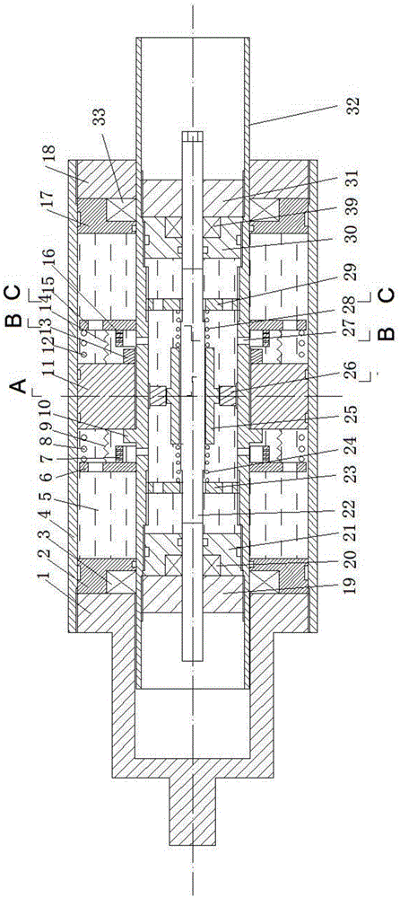
Image
Click on the blue label to locate the original text in one second.
Reading with bidirectional positioning of images and text.
Examples
Embodiment Construction
[0030] The present invention will be further described in detail below in conjunction with the accompanying drawings and embodiments.
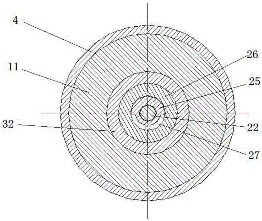
[0031] see figure 2 , image 3 , Figure 4 , Figure 5 , this embodiment includes the outer cylinder 4 of the cylinder, the piston 11, the piston rod 32, and the viscous fluid 5 in the cylinder; the left end of the outer cylinder 4 is provided with a left outer end cover 1 and a left outer sealing seat 2 from outside to inside, The piston rod 32 in the left outer seal seat 2 is nested with the left outer seal ring 3; The piston rod 32 is nested with a right outer sealing ring 33; the left and right outer end caps are threadedly connected to the inner wall of the outer cylinder; steps are provided on the outer circumferential surfaces of the left and right outer sealing seats to coordinate with the steps on the inner wall of the outer cylinder. Sealing rings are arranged between the left and right outer sealing seats and the inner wall of ...
PUM
Abstract
The invention discloses an external adjustable viscous damper with a function of speed and displacement locking. The external adjustable viscous damper comprises a cylinder block, a piston, a piston rod, vicious fluid, end covers, sealing seats, sealing rings, a piston rod shaft shoulder, a compression nut, a left limiting block, a right limiting block, a left limiting ring, a right limiting ring, a left outer pressure spring, a left tension spring, a right outer pressure spring, a right tension spring, a piston rod spool, a flow-limiting ring seat, a left adjusting nut, a right adjusting nut, a left inner pressure spring, a right inner pressure spring, an adjusting rod, a left inner sealing seat, a right inner sealing seat, a left inner sealing ring, a right inner sealing ring, a left inner end cover and a right inner end cover. The end covers, the sealing seats and the sealing rings are disposed at two ends of an outer barrel of the cylinder block. The left limiting block, the right limiting block, the left limiting ring, the right limiting ring, the piston rod, the left adjusting nut and the right adjusting nut are provided with throttle orifices. The external adjustable viscous damper has the functions of speed limiting, displacement limiting and pressure limiting, rigid contact between the piston and the cylinder block can be prevented, damping force is adjustable, and alpha value of the damping force F is reduced.
Description
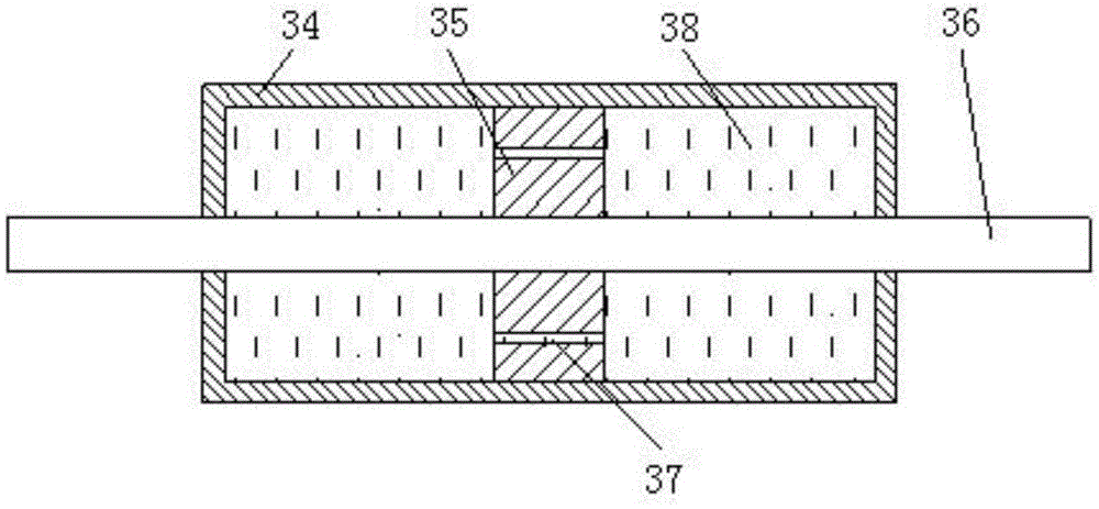
technical field [0001] The invention belongs to the technical field of anti-vibration and vibration reduction of structures or bridges, and in particular relates to a velocity-displacement double-lock externally adjustable viscous damper. Background technique [0002] Large structures such as high-rise buildings and long-span bridges will vibrate greatly under the action of earthquake or wind, and the large vibration of the structure will lead to the destruction of some of its components or the overall collapse. In order to reduce the impact of earthquake or wind on structures, oil dampers are widely used in building structures and bridge structures for energy dissipation and vibration reduction. The structure of the oil damper generally adopts the shear valve type, such as figure 1 as shown, figure 1 Among them, 34 is a cylinder block, 35 is a piston, 36 is a piston rod, 37 is an orifice, and 38 is a viscous fluid. [0003] The vibration reduction effect of the damper de...
Claims
Application Information
Patent Timeline
Application Date:The date an application was filed.
Publication Date:The date a patent or application was officially published.
First Publication Date:The earliest publication date of a patent with the same application number.
Issue Date:Publication date of the patent grant document.
PCT Entry Date:The Entry date of PCT National Phase.
Estimated Expiry Date:The statutory expiry date of a patent right according to the Patent Law, and it is the longest term of protection that the patent right can achieve without the termination of the patent right due to other reasons(Term extension factor has been taken into account ).
Invalid Date:Actual expiry date is based on effective date or publication date of legal transaction data of invalid patent.

