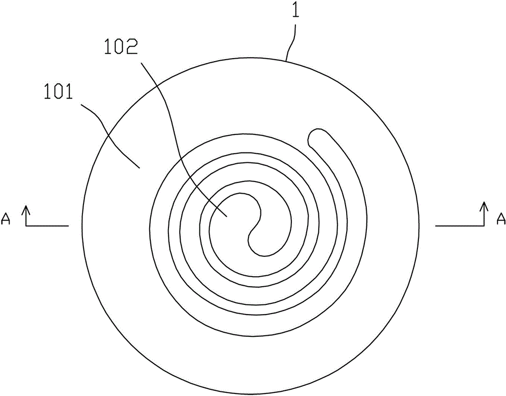
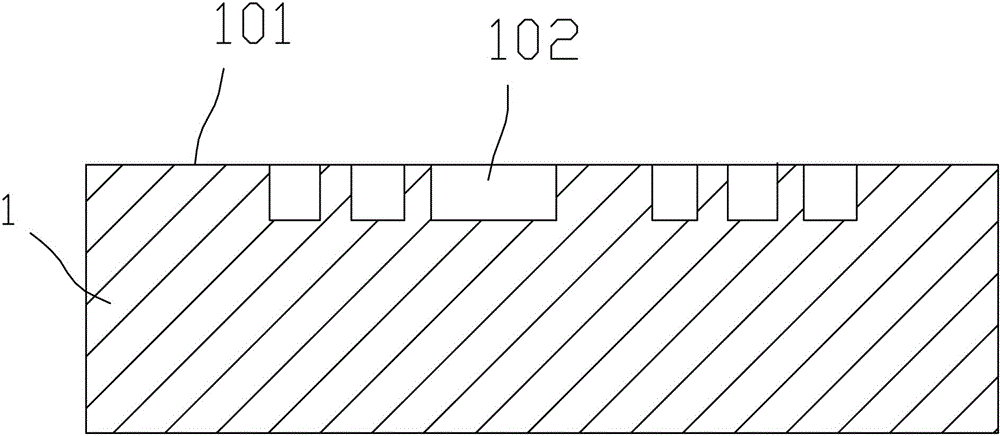
Static scroll plate on scroll compressor, and production method thereof
A technology of scroll compressors and fixed scrolls, applied in the direction of rotary piston machinery, rotary piston/swing piston pump components, mechanical equipment, etc., can solve the problem of reduced output air pressure, failure to meet the use requirements, wear, etc. problems, to avoid the reduction of output air pressure, high reliability, and ensure normal use
- Summary
- Abstract
- Description
- Claims
- Application Information
AI Technical Summary
Problems solved by technology
Method used
Image
Examples
Embodiment 1
[0017] The manufacturing method of the fixed scroll on the scroll compressor of the present invention includes the following steps:
[0018] (1) The base is made of steel material, and an involute vortex groove is machined on the working end surface of the base. The vortex groove has a bottom surface and two side walls;
[0019] (2) Simultaneously sinter the spherical copper powder layer on the working end surface of the substrate, the bottom surface of the vortex groove and both side walls, and the thickness of the spherical copper powder layer is 1.2mm;
[0020] (3) Put the liquid self-lubricating material in the vacuum furnace, immerse the substrate in the self-lubricating material, and then evacuate the vacuum furnace. After 30 minutes, open the vacuum furnace and take out the substrate to obtain the finished static scroll. , Wherein the self-lubricating material consists of 2.5% by mass molybdenum disulfide and 97.5% by mass polytetrafluoroethylene emulsion.
[0021] When sinteri...
Embodiment 2
[0023] The manufacturing method of the fixed scroll on the scroll compressor of the present invention includes the following steps:
[0024] (1) The base is made of steel material, and an involute vortex groove is machined on the working end surface of the base. The vortex groove has a bottom surface and two side walls;
[0025] (2) Simultaneously sinter the spherical copper powder layer on the working end surface of the substrate, the bottom surface of the vortex groove and both side walls, and the thickness of the spherical copper powder layer is 1.3mm;
[0026] (3) Put the liquid self-lubricating material in the vacuum furnace, immerse the substrate in the self-lubricating material, and then evacuate the vacuum furnace. After 60 minutes, open the vacuum furnace and take out the substrate to obtain the finished static scroll. The self-lubricating material is composed of 3% by mass molybdenum disulfide and 97% by mass polytetrafluoroethylene emulsion.
[0027] When sintering the sphe...
Embodiment 3
[0029] The manufacturing method of the fixed scroll on the scroll compressor of the present invention includes the following steps:
[0030] (1) The base is made of steel material, and an involute vortex groove is machined on the working end surface of the base. The vortex groove has a bottom surface and two side walls;
[0031] (2) Simultaneously sinter the spherical copper powder layer on the working end surface of the substrate, the bottom surface of the vortex groove and both side walls, and the thickness of the spherical copper powder layer is 1.4mm;
[0032] (3) Put the liquid self-lubricating material in the vacuum furnace, immerse the substrate in the self-lubricating material, and then evacuate the vacuum furnace. After 90 minutes, open the vacuum furnace and take out the substrate to obtain the finished static scroll. The self-lubricating material consists of 3.5% molybdenum disulfide and 96.5% polytetrafluoroethylene emulsion.
[0033] When sintering the spherical copper po...
PUM
 Abstract
Description
Claims
Application Information
 - R&D
- Intellectual Property
- Life Sciences
- Materials
- Tech Scout
- Unparalleled Data Quality
- Higher Quality Content
- 60% Fewer Hallucinations
Browse by: Latest US Patents, China's latest patents, Technical Efficacy Thesaurus, Application Domain, Technology Topic, Popular Technical Reports.
© 2025 PatSnap. All rights reserved.Legal|Privacy policy|Modern Slavery Act Transparency Statement|Sitemap|About US| Contact US: help@patsnap.com


