Regional particulate matter stereoscopic monitoring system and method

A monitoring system and particle technology, applied in the direction of particle suspension analysis, measuring device, suspension and porous material analysis, to achieve the effect of three-dimensional monitoring, analysis and judgment

Active Publication Date: 2015-04-01
MAPUNI TECH CO LTD
View PDF7 Cites 23 Cited by
  • Summary
  • Abstract
  • Description
  • Claims
  • Application Information

AI Technical Summary

Problems solved by technology

[0005] The purpose of the present invention is to provide a system and method for three-dimensiona...

Method used


Image

  • Regional particulate matter stereoscopic monitoring system and method
  • Regional particulate matter stereoscopic monitoring system and method

Examples


Embodiment 1

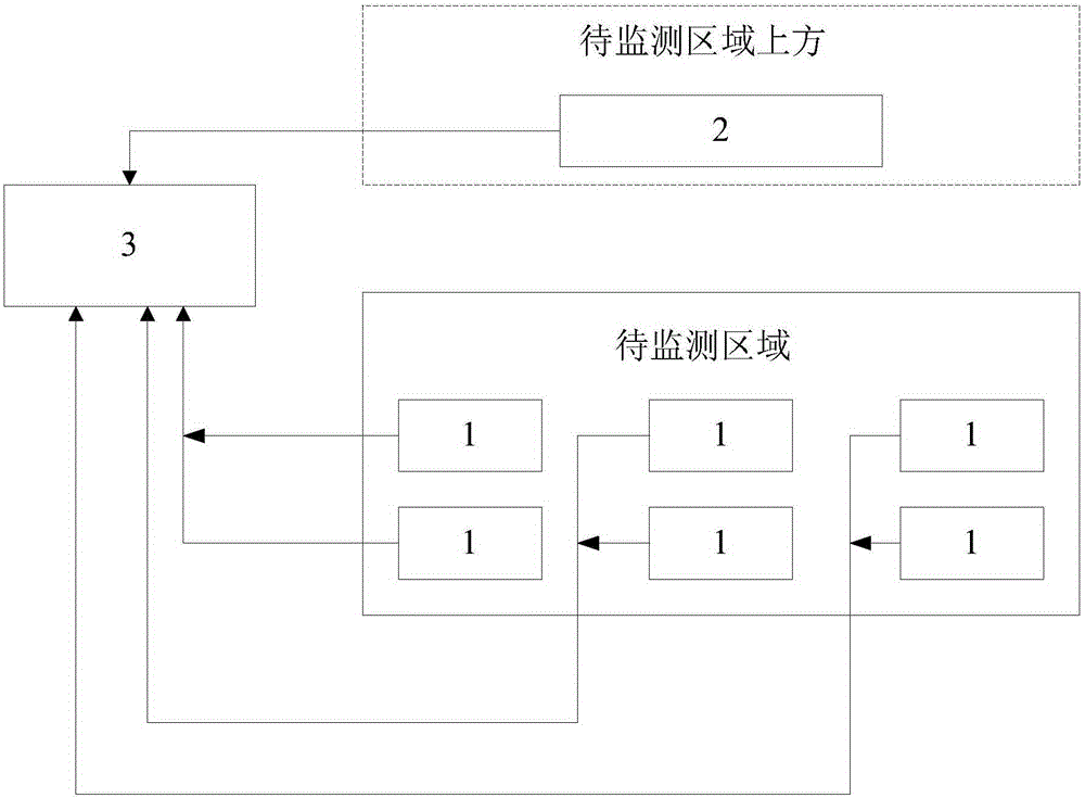
[0033] Such as figure 1 As shown, the embodiment of the present invention provides a three-dimensional monitoring system for regional particulate matter, including:

[0034] Light-scattering particle monitor 1, micro-pulse horizontal scanning laser radar 2 and industrial computer 3, light-scattering particle monitor 1 is set in the area to be monitored, and all light-scattering particle monitors 1 are located at the same altitude; the micro-pulse level The scanning laser radar 2 is set above the area to be monitored; all the light-scattering particle monitors 1 and the micro-pulse horizontal scanning laser radar 2 are connected to the industrial computer 3 .

[0035] The light-scattering particle monitor is a point-type particle concentration measuring instrument, which can draw the ambient air at the installation site into the instrument, and use a laser to irradiate the air in the analysis room inside the instrument. Scattering effect, so the instrument can measure the inte...

Embodiment 2

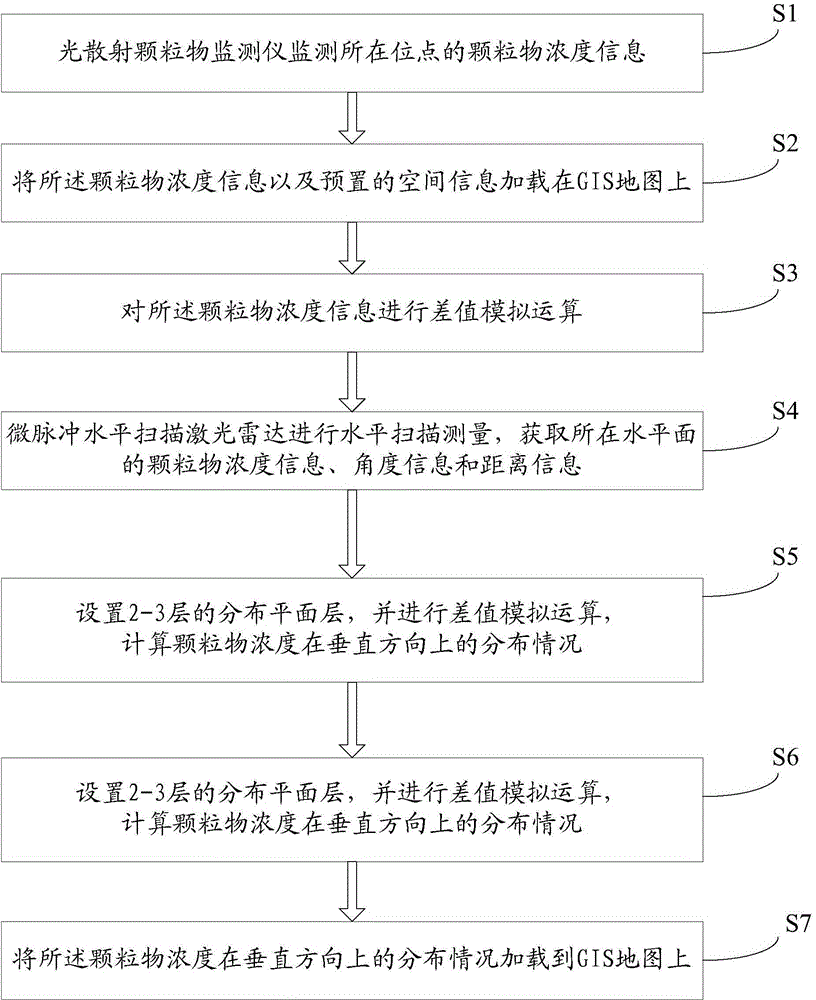
[0070] Such as figure 2 As shown, the embodiment of the present invention also provides a three-dimensional monitoring method for regional particulate matter, using the regional particulate matter three-dimensional monitoring system described in Embodiment 1, including the following steps:

[0071] Step 1, the light-scattering particle monitor monitors the particle concentration information at the location, and transmits the particle concentration information at the location to the industrial computer;

[0072] Step 2, the industrial computer receives the particle concentration information, and loads the particle concentration information and preset spatial information on the GIS map;

[0073] Step 3, performing a difference simulation operation on the particle concentration information, and forming a planar particle concentration distribution layer of the region to be monitored on the GIS map;

[0074] Step 4, the micro-pulse horizontal scanning laser radar performs horizon...


PUM


Abstract

The invention discloses a system and method for stereoscopically monitoring particulate matters in regions such as construction sites, roads and stockyards, and relates to the field of environment monitoring. The system comprises light scattering particulate matter monitors, a micropulse horizontal scanning laser radar and an industrial personal computer, wherein the light scattering particulate matter monitors are arranged in the regions to be monitored and all positioned at the same altitude; the micropulse horizontal scanning laser radar is arranged above the regions to be monitored; all the light scattering particulate matter monitors and the micropulse horizontal scanning laser radar are connected with the industrial personal computer. According to the system and the method, disclosed by the invention, the stereoscopic monitoring to the particulate matter concentration is realized by respectively monitoring the particulate matter concentrations at high level and low level and utilizing a three-dimensional technology and a different value simulating operation technology of GIS (Geographic Information System) to obtain the stereoscopic distribution diagram of the particulate matter concentration in the region to be monitored, so as to realize analysis and judgment on the pollution source and the pollution diffusion situation.

Description

technical field [0001] The invention relates to the field of environmental monitoring, in particular to a system and method for three-dimensional monitoring of particulate matter in construction sites, roads, stockyards and other areas. Background technique [0002] The ambient air quality in my country has seriously deteriorated in recent years, and the number of haze days has increased significantly. Through long-term monitoring of particulate matter components, the environmental protection department has basically determined that 10% to 20% of urban ambient air particulate matter is caused by particulate matter. In order to reduce environmental pollution, the state has issued relevant regulations and measures, requiring the control of particulate matter. The monitoring of particulate matter in construction areas, roads, stockyards and other areas has become the daily work of the environmental monitoring department. [0003] At present, people mainly use dustfall samplin...

Claims


Application Information

Patent Timeline
IPC IPC(8): G01N15/06
Inventor 赵汉松姚新房明刘海英陆菲
Owner MAPUNI TECH CO LTD
Why Eureka
Try Eureka