A microstructure array precision machining machine tool with adaptive matching of dynamic characteristics

An adaptive matching, microstructure array technology, applied in the direction of microstructure technology, microstructure device, manufacturing microstructure device, etc., can solve the problems of limited punching accuracy, limited punching accuracy, and large variation of punching force of punching machines, and achieves improved The effect of machining efficiency, improving machining accuracy and reducing motion deviation

Active Publication Date: 2017-10-27
GUANGDONG UNIV OF TECH
View PDF10 Cites 0 Cited by
  • Summary
  • Abstract
  • Description
  • Claims
  • Application Information

AI Technical Summary

Problems solved by technology

The problems existing in the current stamping equipment are: (1) the stamping precision of the stamping machine is limited; (2) the processing efficiency of the stamping machine is not high; (3) the process adjustment of the stamping equipment is relatively complicated
Because the existing technical solution is to add a Z-direction precision stamping mechanism on the conventional XY platform, the overall structure is relatively cumbersome
In addition, the position control system is adopted for the Z-direction movement in the existing technical scheme, and the stamping force changes greatly during the contact stamping stroke of the stamping head with the workpiece, and the displacement control method will lead to limited actual stamping accuracy
However, in order to achieve high stamping precision, the existing technical solutions often require a more complex process adjustment process, and usually sacrifice processing efficiency

Method used


Image

  • A microstructure array precision machining machine tool with adaptive matching of dynamic characteristics
  • A microstructure array precision machining machine tool with adaptive matching of dynamic characteristics
  • A microstructure array precision machining machine tool with adaptive matching of dynamic characteristics

Examples


Embodiment Construction

[0027] The technical solutions of the present invention will be further described below in conjunction with the drawings and specific implementations.

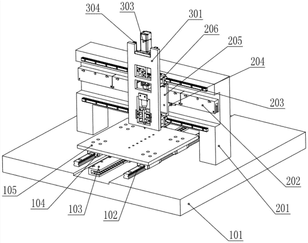
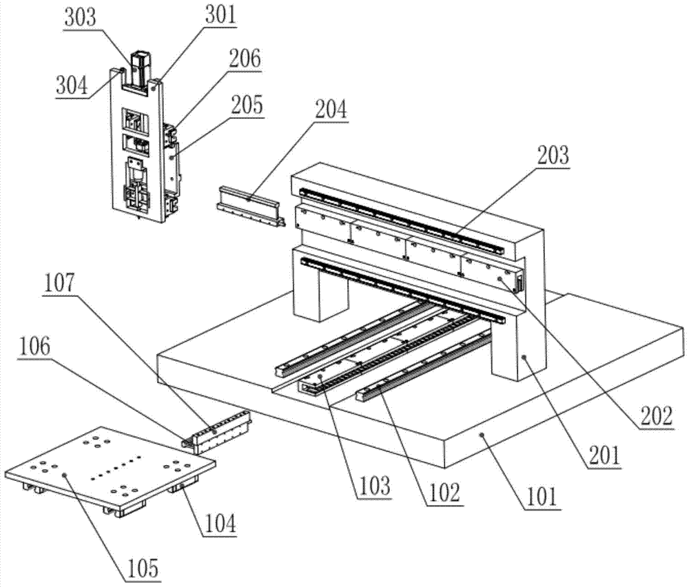
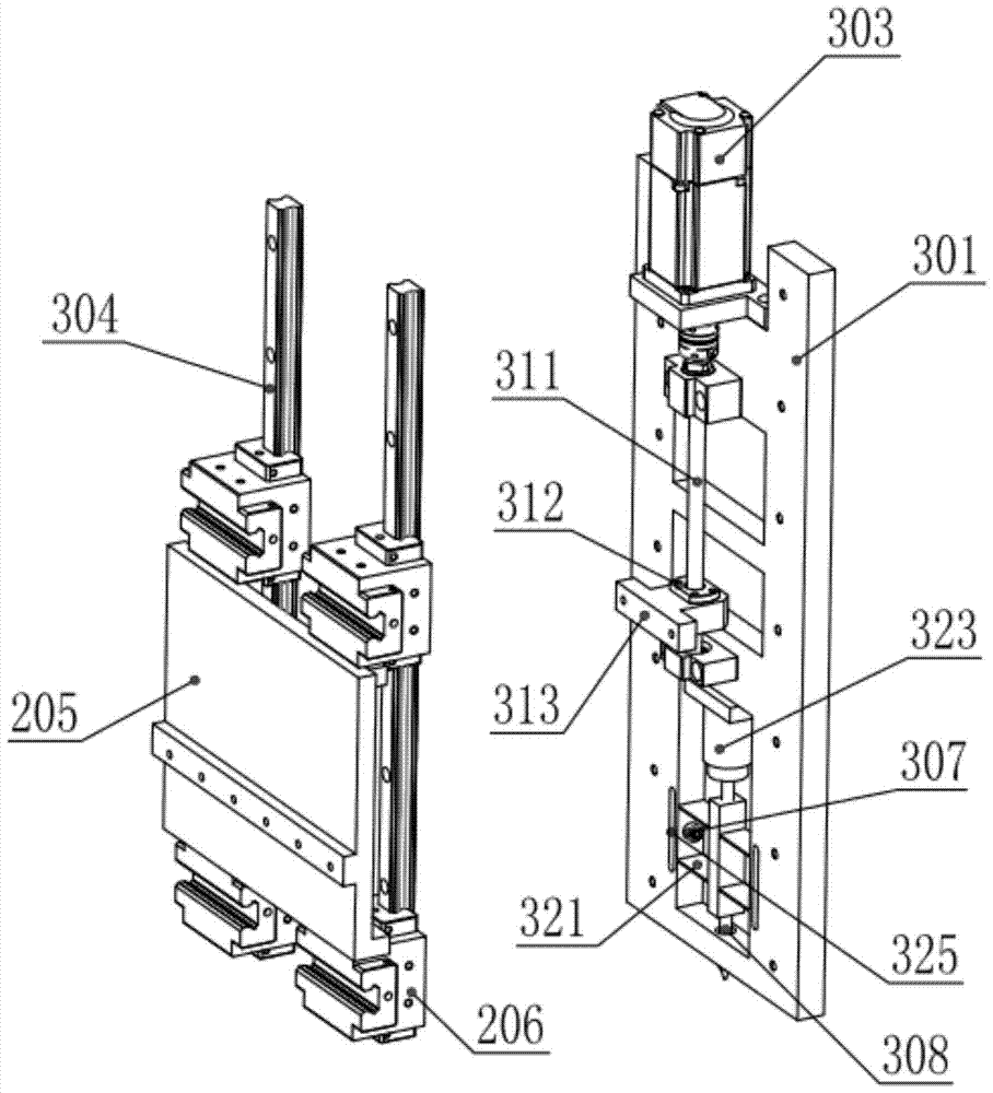
[0028] A microstructure array precision processing machine tool with adaptive dynamic characteristics, comprising a Y-direction movement mechanism 1, an X-direction movement mechanism 2 and a Z-direction precision stamping mechanism 3. The X-direction movement mechanism 2 is fixed to a base through an X-direction bracket 201 101, the Z-direction precision stamping mechanism 3 is installed on the X-direction rail 203 of the X-direction movement mechanism 2 through the X&Z linkage platform 205 and the X&Z composite guide rail slider 206, and is mounted on the X-direction guide rail 203 of the X-direction movement mechanism 2 Driven to achieve X-direction movement;

[0029] The workpiece is placed on the Y-direction movement platform 105 of the Y-direction movement mechanism 1, and the Y-direction movement is realized by the Y-directi...


PUM


Abstract

A microstructure array precision processing machine tool with adaptive matching of dynamic characteristics, including a Y-direction movement mechanism, an X-direction movement mechanism and a Z-direction precision stamping mechanism, the X-direction movement mechanism is fixed on the base through an X-direction bracket, and the Z The X-direction precision stamping mechanism is installed on the X-direction rail of the X-direction movement mechanism through the X&Z linkage platform and the X&Z composite guide rail slider, and realizes the X-direction movement under the X-direction drive of the X-direction movement mechanism; the workpiece is placed on the on the Y-direction motion platform of the Y-direction motion mechanism, and realize the Y-direction motion through the Y-direction motion mechanism. The Z-direction precision stamping mechanism can fine-tune the dynamic characteristics according to different stamping frequencies to obtain consistent dynamic response performance, and can realize position-force switching compound control to achieve consistent processing of microstructure arrays. The invention proposes a precision micro stamping machine tool which shortens alignment time, reduces motion deviation, and improves processing efficiency and processing accuracy.

Description

Technical field [0001] The invention relates to a precision motion platform, in particular to a microstructure array precision processing machine tool with adaptive dynamic characteristics matching. Background technique [0002] In the field of semiconductor packaging, it is often necessary to process some precision microstructures on the workpiece. Precision stamping machine is a processing equipment that completes the above-mentioned procedures. The current problems of stamping equipment include: (1) the stamping accuracy of the stamping machine is limited; (2) the processing efficiency of the stamping machine is not high; (3) the process adjustment of the stamping equipment is more complicated. In the prior art micro-stamping machine tool, a Z-direction precision stamping mechanism is set on the conventional XY platform. In the Z-direction precision stamping mechanism, piezoelectric ceramic actuators and elastic devices are used to drive the micro-stamping head to process a m...

Claims


Application Information

Patent Timeline
Patent Type & Authority Patents(China)
IPC IPC(8): H01L21/50B21D28/02B81C1/00
Inventor 陈新白有盾杨志军王梦高健李涵雄李成祥王江龙黄宇涵刘浩文李振新钟裕导刘伟光杨海东管贻生陈新度
Owner GUANGDONG UNIV OF TECH
Why Eureka
Try Eureka