Switch cabinet valve device and switch cabinet using same

A door device and switchgear technology, applied in the field of switchgear and switchgear shutter device, can solve the problems of restricting the development and application of switchgear, no switchgear shutter device, width limitation of shutter device, etc. The effect of reducing the overall cost

Active Publication Date: 2015-04-01
PINGGAO GRP +1
View PDF4 Cites 10 Cited by
  • Summary
  • Abstract
  • Description
  • Claims
  • Application Information

AI Technical Summary

Problems solved by technology

[0004] The above-mentioned valve technology is mature and widely used, but for the switchgear with the main circuit static contacts arranged in the front, middle and rear, since the static contacts and contact boxes to be covered by the valve are arranged along the depth direction of the cabinet, the depth of the blocked area is very large , and other components

Method used


Image

  • Switch cabinet valve device and switch cabinet using same
  • Switch cabinet valve device and switch cabinet using same
  • Switch cabinet valve device and switch cabinet using same

Examples


Embodiment Construction

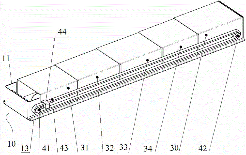
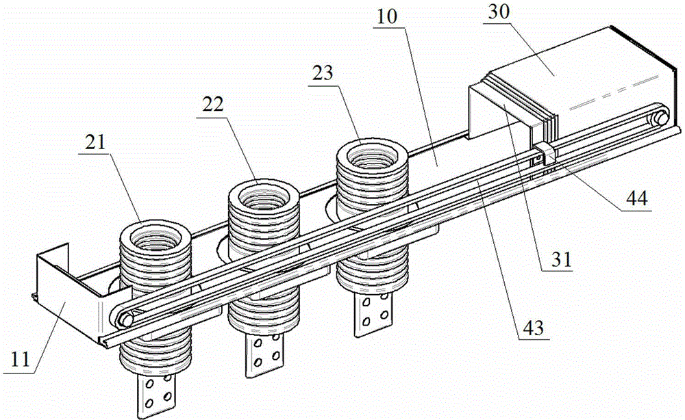
[0022] An embodiment of the switchgear shutter device in the present invention is as Figure 1~Figure 4 As shown, it includes a guide base 10, a fixed shutter 30 and a movable shutter. The guide base 10 is a plate structure, the front end of which is provided with a U-shaped front baffle 11 , and the rear end is provided with a flat rear baffle 12 . The position on the guide base 10 close to the front baffle 11 is the contact installation cavity for installing the static contacts of the main circuit of the switch cabinet. There are three static contacts and contact box installation structures arranged in front and rear at this position. The installation structure of the static contact and the contact box is respectively used to set the static contact 21 of the main circuit of the A phase, the static contact 22 of the main circuit of the B phase and the static contact 23 of the main circuit of the C phase.

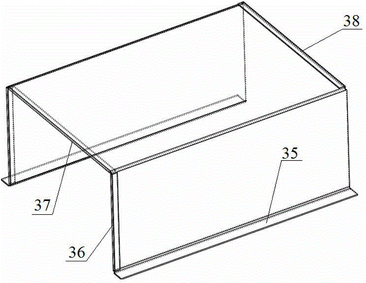
[0023] Both the fixed valve 30 and the movable valve are plate struct...


PUM


Abstract

The invention relates to a switch cabinet valve device and a switch cabinet using the same. The switch cabinet valve device comprises a guide base, wherein the guide base is provided with a touch installation cavity and more than two movable valves, the touch installation cavity is used for installing a stationary contact of a switch cabinet main loop, and the movable valves carry out guide movement along a forward and backward direction, are mutually nested and are successively in telescopic cooperation; the rear part of each movable valve is provided with a rear opening stop structure; the front part of each movable valve is provided with a closing stop structure which is used for carrying out backward stop cooperation with the corresponding closing stop structure arranged on the front part of an adjacent movable valve behind the movable valve; each movable valve is provided with an opening position and a closing position in the guide movement direction of the movable valve; the movable valve used for nesting on an innermost layer is in transmission connection with a driving mechanism used for driving the movable valve to move between the opening position and the closing position. The switch cabinet valve device can meet the use requirements of the switch cabinets arranged from front to rear in sequence in the main loop.

Description

technical field [0001] The invention relates to a switch cabinet shutter device and a switch cabinet using the shutter device. Background technique [0002] For medium-voltage metal-enclosed switchgear with air as the main insulation method, in order to make the loss of continuity category meet the requirements of LSC2B category, when people enter the main switch compartment, there must be a valve to cover the live static contact part, so that people cannot touch. LSC2B is a category of loss of continuity of operation. It is an important content in GB3906-2006, which stipulates that "except for the functional unit that is opened and isolated, all other functional units can continue to operate", which has great impact on the reliability and reliability of equipment. Security means a lot. [0003] At present, the valves of switchgears at home and abroad are designed for medium-voltage switchgear whose main circuit is arranged in the left, middle and right, and the isolation ...

Claims


Application Information

Patent Timeline
IPC IPC(8): H02B1/26
CPCH02B1/14H02B1/26
Inventor 冯祥伟袁端磊朱志豪贾耿峰张永辉朱彦卿
Owner PINGGAO GRP
Why Eureka
Try Eureka