A control method of time standard equipment and time standard equipment

A control method and time standard technology, which is applied in the control of time standard equipment and in the field of time standard equipment, can solve problems such as the inability to frequency lock in the atomic ground state

Active Publication Date: 2017-12-15
JIANGHAN UNIVERSITY
View PDF3 Cites 0 Cited by
  • Summary
  • Abstract
  • Description
  • Claims
  • Application Information

AI Technical Summary

Problems solved by technology

[0006] In order to solve the problem that the existing technology cannot lock the frequency on the atomic ground state hyperfine 0-0 center frequency, the embodiment of the present invention provides a control method of time standard equipment and time standard equipment

Method used


Image

  • A control method of time standard equipment and time standard equipment
  • A control method of time standard equipment and time standard equipment
  • A control method of time standard equipment and time standard equipment

Examples


Embodiment 1

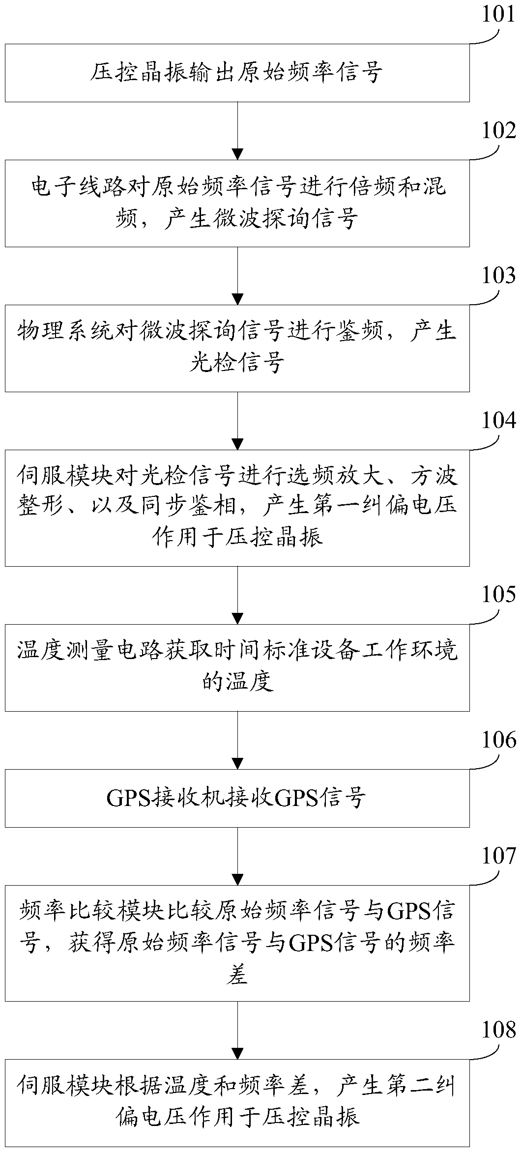
[0066] An embodiment of the present invention provides a control method of a time standard device, see figure 1 , the control method includes:

[0067] Step 101: The voltage-controlled crystal oscillator outputs an original frequency signal.

[0068] Step 102: The electronic circuit performs frequency multiplication and frequency mixing on the original frequency signal to generate a microwave inquiry signal.

[0069] In an implementation manner of this embodiment, step 102 may include:

[0070] An integrated module in the electronic circuit generates an integrated modulation signal;

[0071] The microwave frequency multiplication and mixing module in the electronic circuit simultaneously performs frequency multiplication and frequency mixing on the original frequency signal and the integrated modulation signal to generate a microwave inquiry signal.

[0072] In another implementation manner of this embodiment, before step 102, the control method may further include:

[007...

Embodiment 2

[0115] An embodiment of the present invention provides a time standard device, see Figure 4 , the time standard equipment includes:

[0116] A voltage-controlled crystal oscillator 201, used to output the original frequency signal;

[0117] The electronic circuit 202 is used to perform frequency multiplication and frequency mixing on the original frequency signal to generate a microwave inquiry signal;

[0118] The physical system 203 is configured to discriminate the frequency of the microwave interrogation signal to generate an optical detection signal;

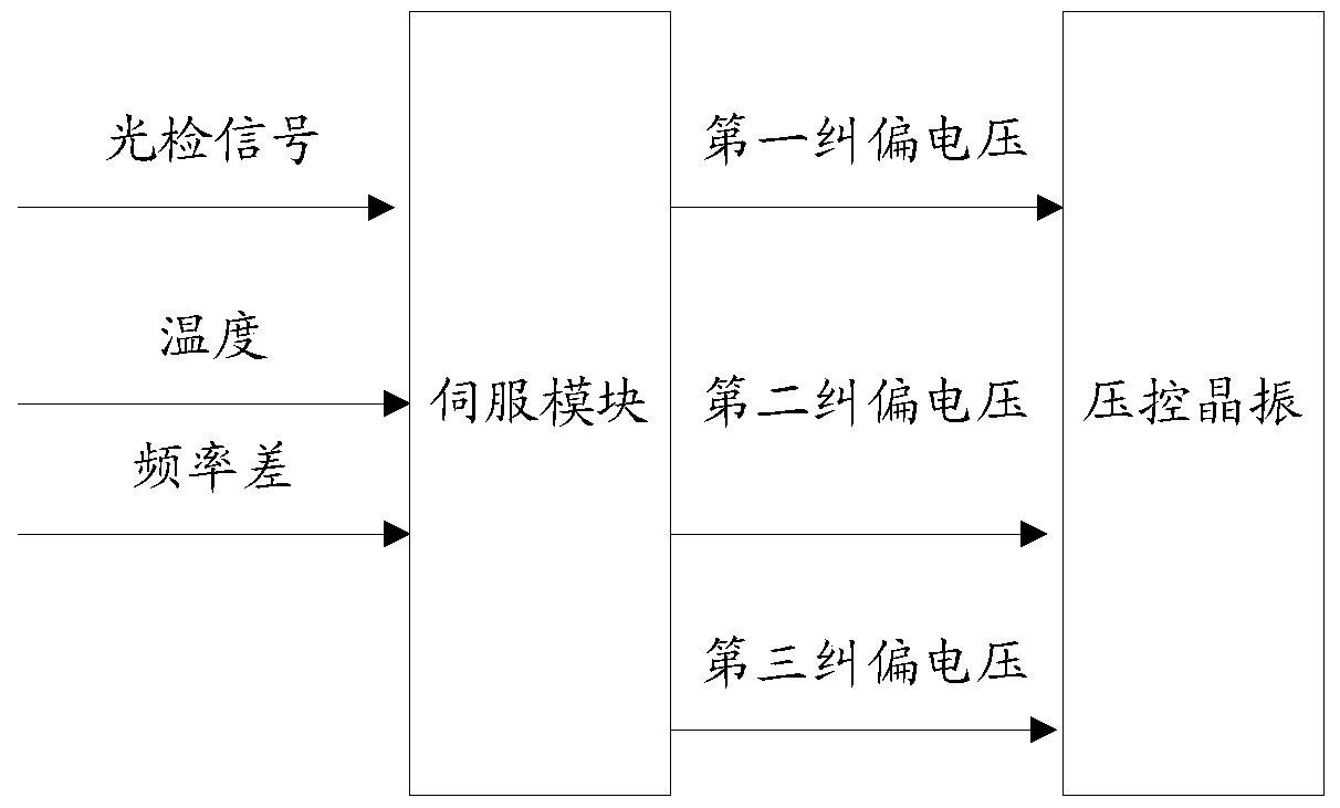
[0119] The servo module 204 is used to perform frequency-selective amplification, square-wave shaping, and synchronous phase detection on the optical detection signal, and generate a first deviation correction voltage to act on the voltage-controlled crystal oscillator 201;

[0120] Temperature measurement circuit 205, used to obtain the temperature of the working environment of the time standard equipment;

[0121] GPS r...


PUM


Abstract

The invention discloses a control method of time standard equipment and the time standard equipment, belonging to the technical field of time standard. The method includes: the voltage-controlled crystal oscillator outputs the original frequency signal; the electronic circuit multiplies and mixes the original frequency signal to generate a microwave inquiry signal; the physical system performs frequency discrimination on the microwave inquiry signal to generate an optical detection signal; The detection signal is subjected to frequency selection amplification, square wave shaping, and synchronous phase detection to generate the first deviation correction voltage to act on the voltage-controlled crystal oscillator; the temperature measurement circuit obtains the temperature of the working environment of the time standard equipment; the GPS receiver receives the GPS signal; the frequency comparison module compares The original frequency signal and the GPS signal obtain the frequency difference between the original frequency signal and the GPS signal; the servo module generates a second deviation correction voltage to act on the voltage-controlled crystal oscillator according to the temperature and frequency difference. The output frequency of the voltage-controlled crystal oscillator of the present invention will not change in a large range due to temperature changes.

Description

technical field [0001] The invention relates to the technical field of time standards, in particular to a control method of time standard equipment and the time standard equipment. Background technique [0002] The atomic frequency standard is a device that provides standard frequency and time, that is, a time standard device. The rubidium atomic frequency standard has become the most widely used atomic frequency standard because of its small size, low power consumption and good ability to withstand harsh environments. It also has good indicators and can meet the needs of most military and civil projects. It can be used in engineering fields such as early warning aircraft, fighter aircraft, electronic countermeasures, third-generation mobile communication technology networks, and power monitoring. [0003] Existing atomic frequency standards include voltage-controlled crystal oscillators, physical systems, electronic circuits, and servo modules. Among them, the voltage-con...

Claims


Application Information

Patent Timeline
Patent Type & Authority Patents(China)
IPC IPC(8): H03L7/099G04R20/04
Inventor 田玉
Owner JIANGHAN UNIVERSITY
Why Eureka
Try Eureka