

Screw loosening prevention structure
A thread and structure technology, applied in the field of preventing thread loosening structure, can solve problems such as thread loosening
- Summary
- Abstract
- Description
- Claims
- Application Information
AI Technical Summary
Problems solved by technology
Method used
Image

Examples
no. 1 Embodiment approach
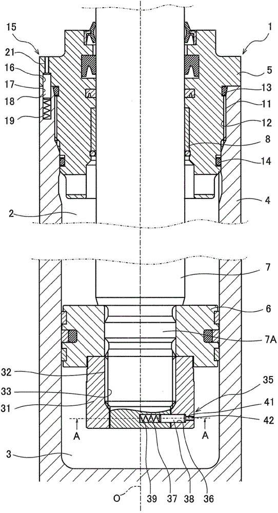
[0017] First, explain figure 1 The hydraulic cylinder (fluid pressure cylinder) 1 shown. This hydraulic cylinder 1 is provided with a screw loosening prevention structure according to an embodiment of the present invention described later.
[0018] The hydraulic cylinder 1 includes a cylindrical cylinder 4 , a piston 6 slidably accommodated inside the cylinder 4 , a piston rod 7 connected to the piston 6 , and a cylinder head 5 slidably supporting the piston rod 7 .
[0019] The inside of the cylinder 4 is divided into a head side chamber 2 and a bottom side chamber 3 by a piston 6 . The head side chamber 2 is provided on the head side where the piston rod 7 protrudes from the cylinder body 4 , and is divided by the cylinder body 4 , the piston 6 , the piston rod 7 and the cylinder head 5 . The bottom side chamber 3 is provided on the bottom side of the cylinder 4 and is divided by the cylinder 4 and the piston 6 .
[0020] When the hydraulic cylinder 1 is extended and oper...
no. 2 Embodiment approach
[0076] Below, refer to Figure 5 A second embodiment of the present invention will be described. In the screw loosening prevention structure 60 of the second embodiment, the second member (the fastened member 54 ) is sandwiched between the first and third members (bolt 55 , main body 53 ) that are screwed together via the threads 51 and 52 . ), and the pin 63 is interposed between the first and second members (bolt 55, fastened member 54).
[0077] The fastened member 54 is fastened to the main body 53 with bolts 55 . Bolt holes 56 through which bolts 55 penetrate are formed in the fastened member 54 . The external thread 51 is formed in the threaded portion 55B of the bolt 55 , while the internal thread 52 is formed in the screw hole 53A of the main body 53 .
[0078] Between the bolt 55 and the member to be fastened 54, a screw loosening prevention structure 60 that restricts relative rotation of both is provided.
[0079] The screw loosening prevention structure 60 incl...
no. 3 Embodiment approach
[0092] Below, refer to Figure 6 A third embodiment of the present invention will be described. In the screw loosening prevention structure 70 of the third embodiment, the third member (the fastened member 54 ), insert the pin 73 into the first, second, and third members (bolt 55, main body 53, fastening member 54). The same reference numerals are assigned to the same configurations as those in the second embodiment described above, and description thereof will be omitted. In addition, in the second embodiment described above, the first member is the bolt 55 , the second member is the fastened member 54 , and the third member is the main body 53 . On the other hand, in this third embodiment, the first member is the bolt 55 , the second member is the main body 53 , and the third member is the fastened member 54 .
[0093] Between the bolt 55 , the fastened member 54 , and the main body 53 , a screw loosening prevention structure 70 that restricts relative rotation of each i...
PUM
 Abstract
Description
Claims
Application Information