Returned power for microwave applications

A technology of power and microwave energy, applied in microwave heating, microwave surgical instruments, components of surgical instruments, etc., can solve problems such as system performance deterioration

Active Publication Date: 2015-04-01
MICROCUBE
View PDF12 Cites 8 Cited by
  • Summary
  • Abstract
  • Description
  • Claims
  • Application Information

AI Technical Summary

Problems solved by technology

Therefore, any change in the surrounding medium or in the antenna itself during use can cause a sufficientl

Method used


Image

  • Returned power for microwave applications
  • Returned power for microwave applications
  • Returned power for microwave applications

Examples


Embodiment Construction

[0045] This specification discloses multiple antenna designs, systems, structures and devices, and related methods, which illustrate various aspects of the present invention. Although these systems, structures and devices, and related methods are discussed primarily in terms of some specific antenna designs and some representative target materials, the methods and devices disclosed herein are applicable for use in other antenna and system designs and among other target materials.

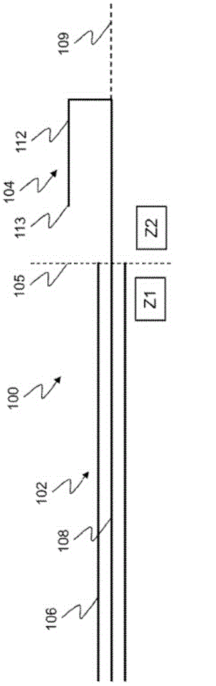
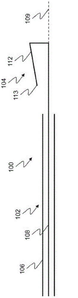
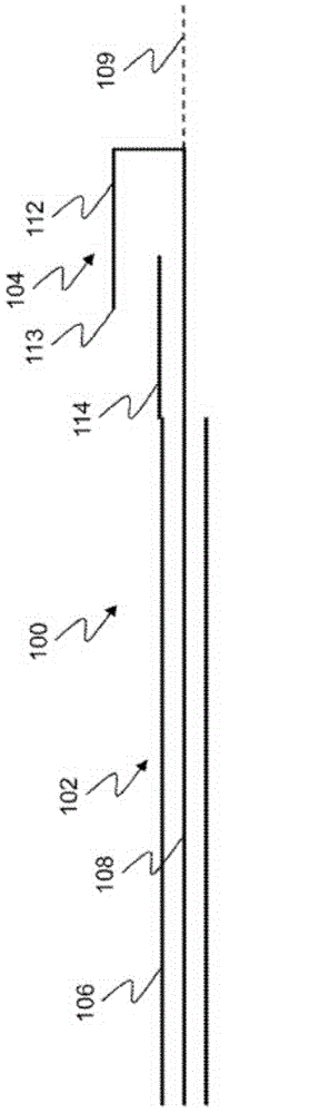
[0046] Figure 1A and 1B A schematic diagram of an embodiment of a microwave device 100 of the present invention having a microwave antenna 104 comprising a flexible radiating element 112 is shown. exist Figure 1A In the microwave device 100 includes a transmission line, such as a coaxial cable 102 . Antenna 104 is connected to the distal end of coaxial cable 102 . Figure 1A The microwave device 100 is shown divided into a first zone Z1 and a second zone Z2 by an imaginary transition line 105 . ...


PUM


Abstract

The present invention related to devices and methods that use returned power (RP) measurements during microwave energy delivery to perform one or more functions. For example, microwave devices and systems that comprise one or more features to measure the returned microwave power. One or more measurements of the returned microwave power may be used to obtain information about one or more of: antenna shape, system status and system performance. One or more measurements of the returned microwave power shaping elements may also be used to obtain information about one or more properties of the target material. The invention also discloses devices and methods for delivering microwave energy to a variety of target materials to achieve a variety of desired microwave effects.

Description

[0001] Cross-references to relevant application data [0002] This application claims priority to US Provisional Application Serial No. 61 / 686,125, filed March 31, 2012, which is hereby incorporated by reference in its entirety. technical field [0003] The present invention relates to apparatus and methods for using return power (RP) measurements to perform one or more functions during transmission of microwave energy. Background technique [0004] A typical microwave antenna designed to transmit microwave energy includes one or more metallic conductors electrically connected to a microwave generator by a transmission line. In use, the antenna acts as an impedance transformer between the microwave source and the medium to which the system transmits microwave energy. From the point of view of the circuit, the medium corresponds to the load in which the microwave energy from the microwave generator is finally stored. [0005] The impedance of the antenna is typically matche...

Claims


Application Information

Patent Timeline
IPC IPC(8): G01R27/04
CPCH05B6/705H05B6/72A61B18/1815H05B1/025A61B2018/00267A61B2018/00642A61B2018/00785A61B2018/1846A61B2018/00708A61B2018/00755A61B2018/00875H05B6/6447H05B6/664
Inventor 进耀·朱迪内希· I·莫迪卡坦·绍夫阿莫瑞什·J·沃克卡比·蒋克里斯多夫·阿·纽克莉丝汀·M·塔特
Owner MICROCUBE
Why Eureka
Try Eureka