Magneto dielectric composite materials and microwave applications thereof

a composite material and magneto dielectric technology, applied in the direction of resonant antennas, substantially flat resonant elements, transportation and packaging, etc., to achieve the effects of strong magnetization, energy efficiency, and space and energy efficiency

Active Publication Date: 2019-07-30
UCHICAGO ARGONNE LLC
View PDF1 Cites 7 Cited by
  • Summary
  • Abstract
  • Description
  • Claims
  • Application Information

AI Technical Summary

Benefits of technology

[0009]An additional object of the invention is to provide an antenna where its impedance is controllable by substrate materials composition. A feature of the invention is that the addition of magnetic loading allows the tuning or matching of impedance within the antenna substrate material (by tuning the ratio of magnetic permeability and dielectric permittivity. A benefit of the invention is that impedance matching can be achieved without resorting to adjusting the geometry of the antenna, which removes significant constraints on antenna design.
[0010]A further object of the invention is to provide a signal reception composite which does not contain conductive paths. A feature of the system is that, in one embodiment, the nanofiber layer is coated with Al2O3. In further embodiments, the coating includes other oxides such as NiO and Fe2O3, or Co3O4. A benefit of the system is that it allows for use of metallic magnetic materials without creating the risk of forming conductive paths within the composite that would render the substrate an unsuitable antenna.
[0011]Another object of the invention is to provide a signal reception composite having metallic magnetic elements. A feature of the invention is that it uses nanofiber structure combined with Al2O3 coating which allows for introduction of metallic magnetic materials. A benefit of the invention is that it has much stronger magnetization than oxide materials such as ferrite, which could not be used in conventional applications because of the high electrical loss
[0012]An additional object of the invention is to provide an adaptive antenna array, which can identify the spatial direction of signal arrival and adapt the radiation pattern to focus at the signal source. A feature of the

Problems solved by technology

Traditionally, due to limitations inherent in materials, radio wave reception antennas had to be built and optimized to receive only a nar

Method used


Image

  • Magneto dielectric composite materials and microwave applications thereof
  • Magneto dielectric composite materials and microwave applications thereof
  • Magneto dielectric composite materials and microwave applications thereof

Examples


embodiment 200

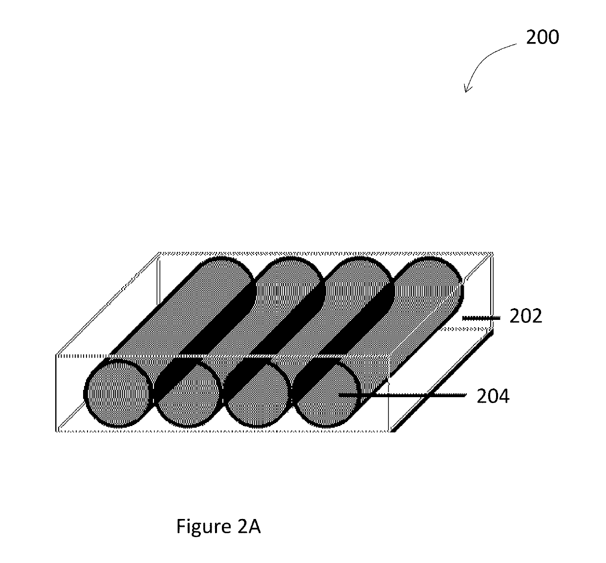
[0046]Shown in FIG. 2A is an overview of an embodiment 200 of the invented substrate. The substrate contains magnetic elements, nanofibers 204 embedded within a dielectric layer 202. In another embodiment similar in appearance to FIG. 2A, the fibers 204 are magnetic, but the dielectric layer 202 comprises a piezoelectric polymer, such as Polyvinylidene fluoride (PVDF), in one embodiment. In this embodiment, the substrate includes a piezoelectric component yet eliminates the need for additional piezoelectric coating described below.

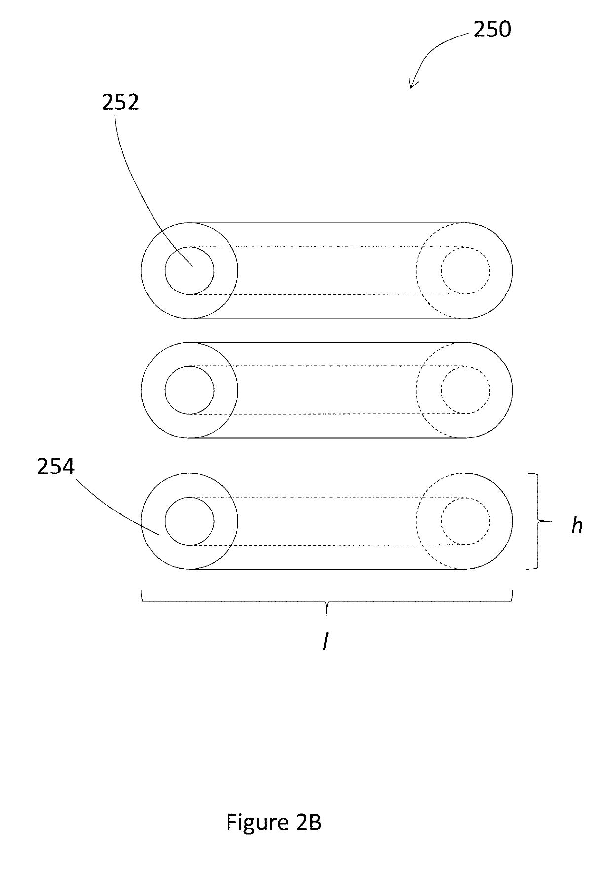
[0047]As shown in FIG. 2B, the individual nanofibers 252 comprising the nanofiber-enriched dielectric layer 250 are substantially parallel. The nanofibers have a high aspect ratio, meaning the ratio of length l to diameter (diameter designated as height h) of each nanofiber 254 is 50:1 or higher. While in FIG. 2B, the nanofibers 254 are shown to be approximately equivalent in length, the equivalent length of nanofibers is not a structural requirement. The ...

embodiment 300

[0057]Turning to, FIG. 3A, depicted therein is a cross section of embodiment 300 of the dielectric layer of the invention. The dielectric layer 302 is enriched by magnetic nanofibers 304. A ferroelectric layer 308, having piezo electric components, described infra, is also added.

embodiment 320

[0058]An alternative embodiment 320 is depicted in FIG. 3B. In the alternative embodiment, the dielectric polymer layer 324 contains coated nanofibers 326 embedded in the layer 324. The nanofibers 326 having a ferroelectric layer 322 added thereon. The nanofibers 326 are magnetic while the polymer and the ferroelectric layer 322 coatings are piezoelectric.


PUM

PropertyMeasurementUnit
Dielectric polarization enthalpyaaaaaaaaaa
Diameteraaaaaaaaaa
Lengthaaaaaaaaaa

Abstract

A system for incorporating ferromagnetic materials into several microwave application is described. The system employs a multi-layer substrate. A substrate for receiving microwave signals uses a base layer which has tunable elements and a nanofiber layer which uses magnetic nanotubes. The nanofibers have a high aspect ratio and the nanofiber layer is embedded in the base layer.

Description

PRIORITY CLAIM[0001]This application claims priority as a continuation in part of U.S. application Ser. No. 15 / 240,168, filed on Aug. 18, 2016, presently pending, which in turn claims priority as a continuation of Ser. No. 14 / 803,339, filed on Jul. 20, 2015, presently abandoned, the contents of each of which are hereby incorporated by reference. This application also claims priority as a continuation in part of U.S. application Ser. No. 15 / 082,901 filed on Mar. 28, 2016, presently pending, which in turn claimed priority as a continuation in part of U.S. application Ser. No. 14 / 803,339, filed on Jul. 20, 2015, presently abandoned, the contents of each of which are hereby incorporated by reference.CONTRACTUAL ORIGIN OF THE INVENTION[0002]The U.S. Government has rights in this invention pursuant to Contract No. DE-AC02-06CH11357 between the U.S. Department of Energy and UChicago Argonne, LLC, representing Argonne National Laboratory.BACKGROUND OF THE INVENTION1. Field of the Invention[...

Claims


Application Information

Patent Timeline
IPC IPC(8): D01D5/00B33Y10/00B33Y30/00
CPCD01D5/0092B33Y30/00B33Y10/00D10B2401/00H01Q9/0442H01Q9/0407B22F1/0547H01Q1/00
Inventor CHEN, XINGZHOU, ZIYAO
Owner UCHICAGO ARGONNE LLC
Why Eureka
Try Eureka