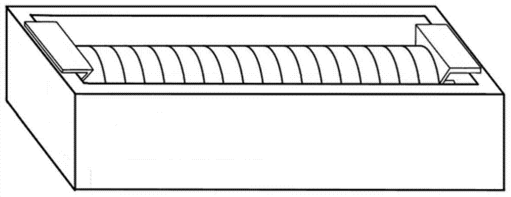
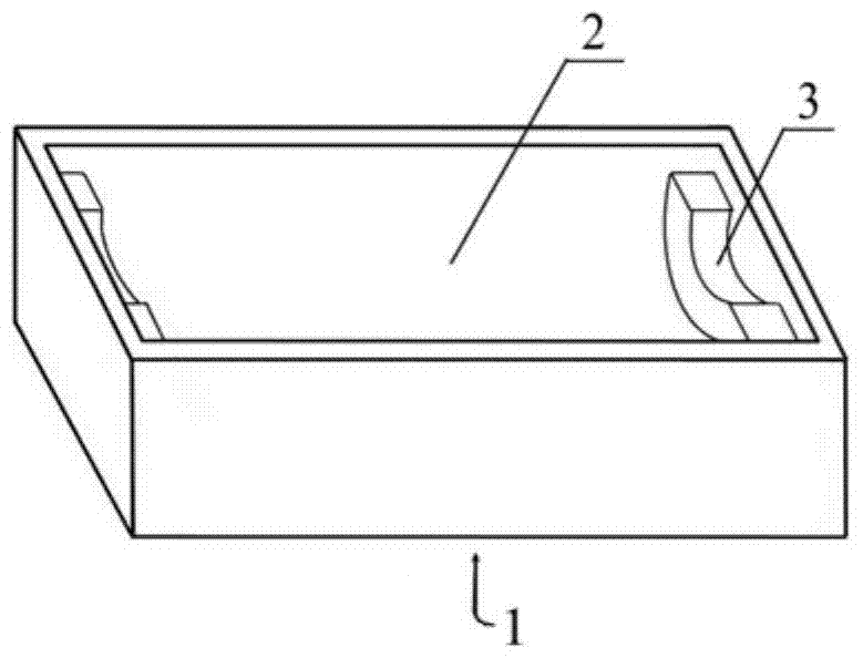
Small surface mount magnetically shielded power inductor and manufacturing method thereof

A surface mount, power inductor technology, applied in the field of inductors, can solve the problems of large volume, small inductance value, small rated current value, etc., to achieve the effect of small inductance, strong anti-saturation magnetization ability, and easy installation.

Active Publication Date: 2017-12-15
江西尚朋电子科技有限公司
View PDF4 Cites 0 Cited by
  • Summary
  • Abstract
  • Description
  • Claims
  • Application Information

AI Technical Summary

Problems solved by technology

If it is necessary to meet the requirements of small size and high inductance value, it can be realized by using enameled wire with thinner wire diameter to wind more turns, but its rated current value is very small; if it needs to meet the requirements of small size and high current resistance, then Enameled wire with thicker wire diameter can be wound with fewer turns, but its inductance value is small; if you need to meet the requirements of high inductance value and high current resistance, you can use enameled wire with thicker wire diameter to wind more The number of turns can be realized, but its volume will be seriously large

Method used


Image

  • Small surface mount magnetically shielded power inductor and manufacturing method thereof
  • Small surface mount magnetically shielded power inductor and manufacturing method thereof
  • Small surface mount magnetically shielded power inductor and manufacturing method thereof

Examples


preparation example Construction

[0036] NiZn ferrite material preparation method of the present invention, comprises the following steps:

[0037] 1. Formulation: 49.0~50.8mol% Fe is used 2 o 3 , 28.0~30.0mol%ZnO, 6.0~8.0mol%CuO, the balance being NiO; 2. One-time ball milling: mix the above powders evenly in the ball mill for 2-4 hours; The ball mill is dried and pre-fired in a furnace at 850-950°C for 2-4 hours; 4. Doping: Add the following dopant to the powder obtained in step 3 by weight ratio: 0.10-0.25wt% Bi 2 o 3 , 0.065~0.125wt%MoO 3 , 0.02~0.075wt%CaCO 3 5. Secondary ball milling: mill the powder obtained in step 4 in a ball mill for 3 to 6 hours; 6. Molding: add 12 to 16 wt% organic binder to the powder obtained in step 5 by weight, mix evenly, After granulation, press the granular powder into a blank on a press; 7. Sintering: put the green body obtained in step 6 into a sintering furnace for sintering, and keep it warm at 1050-1120° C. for 3-5 hours.

[0038] Second, power inductors

[0039]...

Embodiment 3~8

[0062] 1. Shell core

[0063] 1. Formula

[0064] Component Fe 2 o 3 The contents of , ZnO and CuO are respectively 49.4, 29.0 and 6.5mol%, and the balance is NiO;

[0065] 2. One ball milling

[0066] Mix the above powders evenly in a ball mill for 3 hours;

[0067] 3. Pre-burning

[0068] Dry the ball mill material obtained in step 2, and pre-fire it in a furnace at 930°C for 3 hours;

[0069] 4. Doping

[0070] Add the following dopant by weight ratio to the powder obtained in step 3: 0.15wt%Bi 2 o 3 , 0.080wt%MoO 3 , 0.040wt%CaCO 3 ;

[0071] 5. Secondary ball milling

[0072] The powder obtained in step 4 was ball milled in a ball mill for 4 hours;

[0073] 6. Forming

[0074] Add 15wt% organic binder to the powder obtained in step 5 by weight, mix evenly, and granulate, then sieve with a 40-mesh sieve, and get the powder granules whose particle size is between 40 mesh and 200 mesh. Add 0.5% zinc stearate to the selected powder and pellets, use a shell magn...


PUM

PropertyMeasurementUnit
Curie pointaaaaaaaaaa
diameteraaaaaaaaaa
lengthaaaaaaaaaa

Abstract

The invention discloses a small surface-mounted magnetic shielding power inductor and a preparation method thereof, belonging to the technical field of inductors. The small surface-mounted magnetic shielding power inductor of the present invention includes a shell magnetic core, a core core and a coil, the coil is arranged around the core core, and the shell core A limit mechanism is set inside the core, and the inner core and coil are set in the shell core through the limit mechanism. The beneficial effects of the present invention are as follows: first, the inductance is small in size and low in installation height; second, the metal magnetic powder core is used as the core magnetic core, and the inductance can carry a large current because of its strong anti-saturation magnetization ability; third, the use of Core cores of different sizes and coils with different turns realize serialization of inductance values; fourth, surface mount design is adopted, which is easy to install.

Description

technical field [0001] The invention belongs to the technical field of inductors, and in particular relates to the design and manufacture of small surface-mounted and large-current magnetic shielding power inductors. Background technique [0002] The world's electronic components are developing in the direction of small size, high efficiency, surface mount mounting, low surface mounting height, low weight, and low electromagnetic interference, and power inductors must follow the pace of development. Power inductors are widely used in switching power supplies and play a filtering role in the circuit, and their performance directly affects the performance of switching power supplies. For example, low installation height and small volume will greatly reduce the size of switching power supply and increase its power density; high inductance value will reduce the ripple size of switching power supply; low leakage magnetic field will not interfere with other electronics The normal...

Claims


Application Information

Patent Timeline
Patent Type & Authority Patents(China)
IPC IPC(8): H01F17/04H01F27/24H01F27/30H01F1/34H01F41/02H01F41/00
Inventor 余忠孙科赖敏敏李垚蒋晓娜兰中文
Owner 江西尚朋电子科技有限公司
Why Eureka
Try Eureka