
Highly effective brake based on magnetic rheology technique

A brake, magnetorheological technology, applied in the direction of brake type, mechanical equipment, etc., can solve problems such as bulky, achieve the effect of small structure, light weight and energy saving

Inactive Publication Date: 2008-06-25
GUANGDONG UNIV OF TECH
View PDF6 Cites 14 Cited by
  • Summary
  • Abstract
  • Description
  • Claims
  • Application Information

AI Technical Summary

Problems solved by technology

[0004] Xu Jing, Dong Yan's paper "Design and Discussion of Magneto-Rheological Brake" (Mechanical Design and Manufacturing, 2001.01), Yang Yanrong, Shan Huiyong, Wei Yong's paper "Theoretical Design and Analysis of Cylindrical Magneto-Rheological Brake" ( Electromechanical Engineering Technology, 2005.10) etc. described magneto-rheological brakes, but the above-mentioned brakes are all single-stage structures. As the braking torque increases, the volume and weight of the brakes also increase. For example, the 500Nm The size of the brake is already very large, and requires a very large control current

Method used


Image

  • Highly effective brake based on magnetic rheology technique
  • Highly effective brake based on magnetic rheology technique
  • Highly effective brake based on magnetic rheology technique

Examples


Embodiment

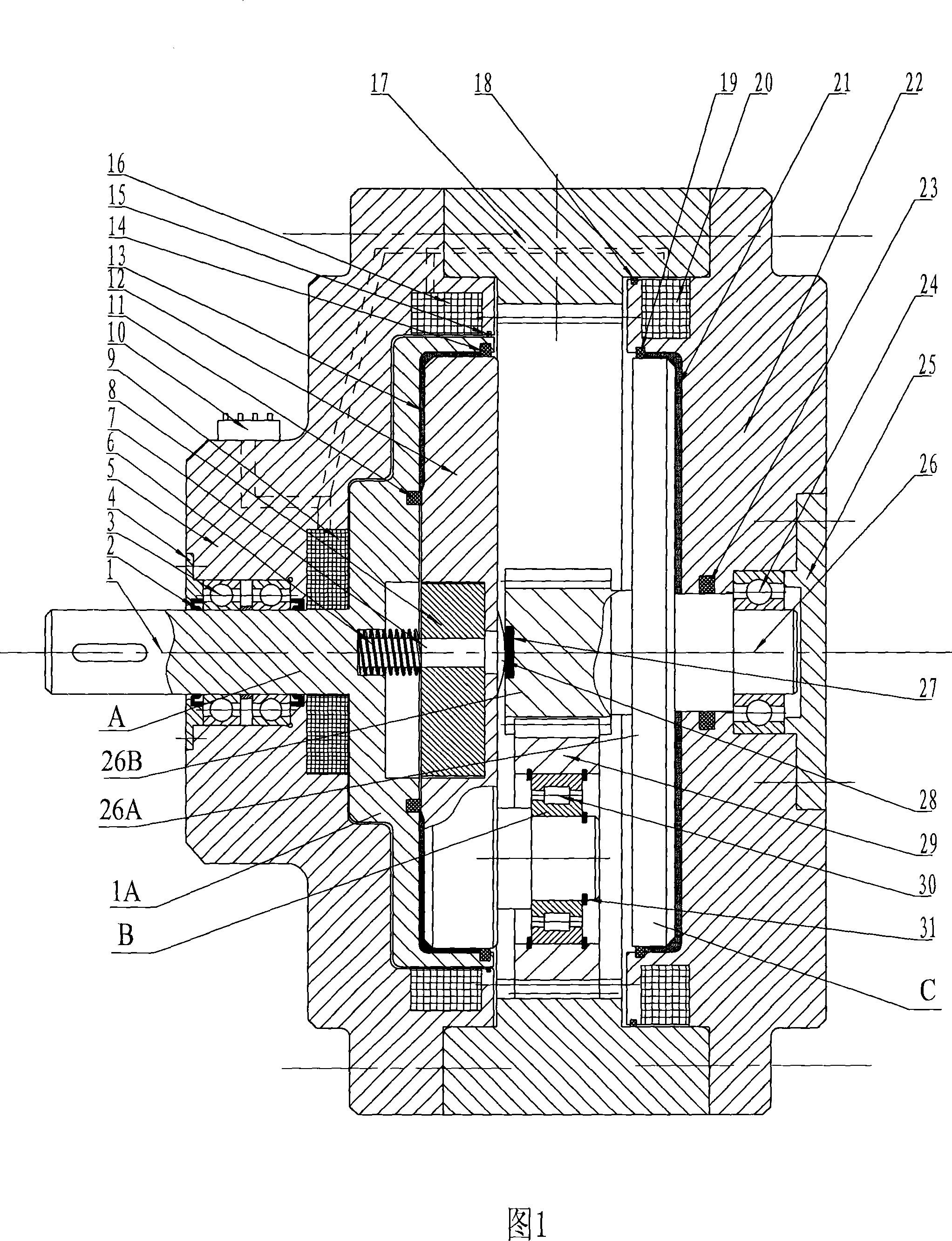
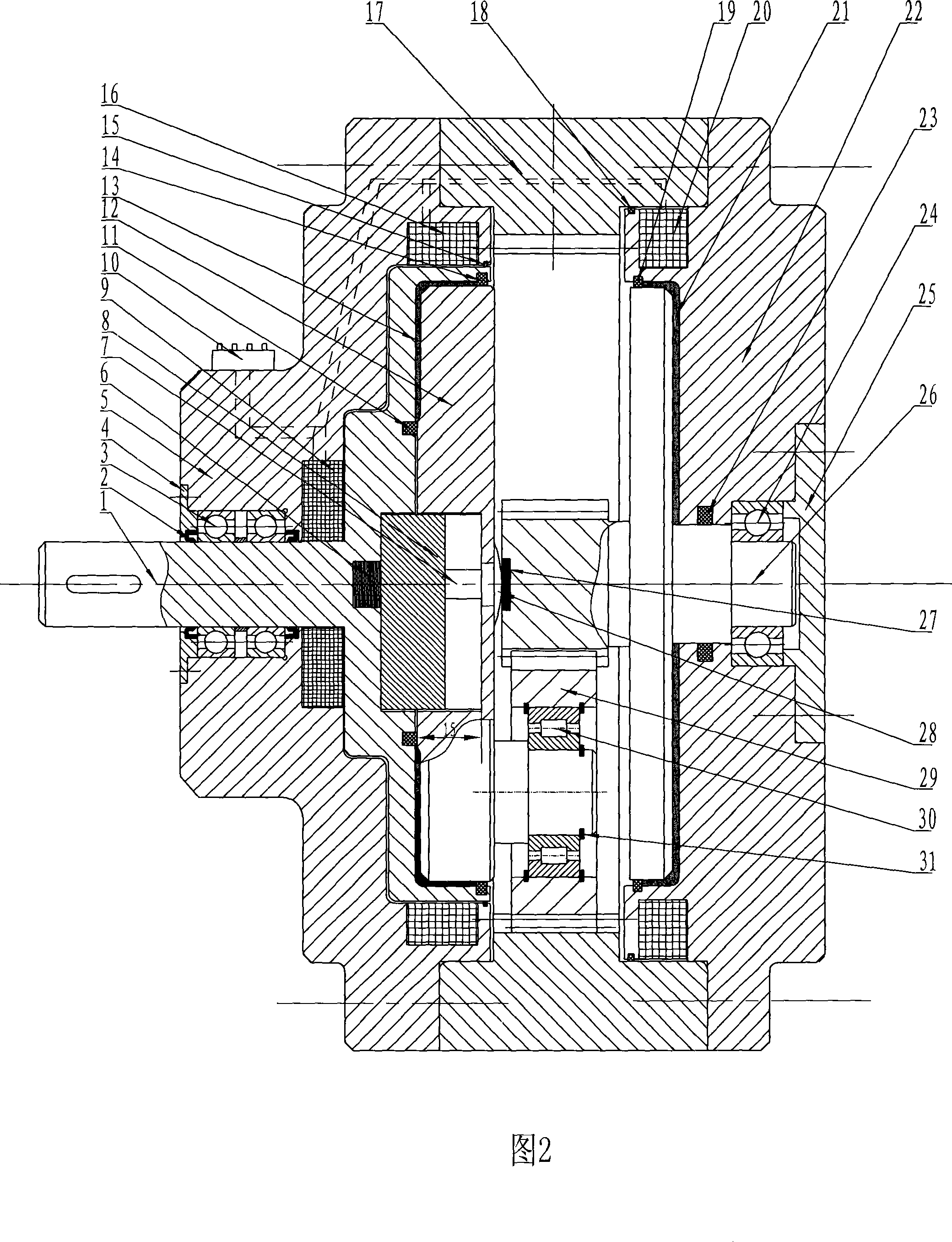
[0023] The structure schematic diagram of the present invention is shown in Figure 1, including the electromagnetic clutch mechanism A and the electromagnetic brake mechanism B that generate the damping torque, wherein a planetary speed increaser that amplifies the damping torque is arranged between the electromagnetic clutch mechanism and the electromagnetic brake mechanism c.

[0024] In this embodiment, the above-mentioned electromagnetic clutch mechanism A includes an input shaft 1 having a disc structure 1A, a left end cover 5 is set on the input shaft 1, and an input excitation coil 9 is set on the contact surface between the input shaft 1 and the left end cover 5 , the contact surface between the disc structure 1A and the left end cover 5 is set with a left excitation coil 16; the electromagnetic brake mechanism B includes a central shaft 26 with a disc structure 26A, and a right end cover 22 is set on the central shaft 26, and the right end cover The outer side of 22 i...


PUM


Abstract

The invention relates to a high-efficiency brake based on the MR technology, which comprises an electromagnetic clutch mechanical (A) producing a damping moment and an electromagnetic braking mechanism (B), wherein a planet accelerator (C) capable of amplifying the damping moment is arranged between the electromagnetic clutch mechanism and the electromagnetic braking mechanism. As the invention adopts the planet accelerator structure which is capable of amplifying the damping moment and is arranged between the electromagnetic clutch mechanism and the electromagnetic braking mechanism, braking with a great moment can be realized under a minor current through the accelerator, thereby saving energy, and further realizing serialization through changing the speed increasing ratio of the internal accelerator. In addition, the invention with small size and light weight is the high-efficiency brake based on the MR technology with smart design, excellent performance as well as convenience and practicability.

Description

Technical field: [0001] The invention is a high-efficiency brake based on the magneto-rheological technology, which belongs to the transformation technology of the brake based on the magneto-rheological technology. Background technique: [0002] The brake is a device used to reduce the speed of the machine or force the machine to stop. At present, the commonly used brakes include belt type, brake shoe type, point disc type, inner tension shoe type, disc type and other friction brakes and magnetic powder type, magnetic eddy current type, Water eddy current and other non-friction brakes, among which magnetic powder brakes are the most widely used in automatic adjustment control. [0003] Such as U.S.Patent 4,992,190, 5,549,837 and 6,471,018 B1 introduce various dampers of magnetorheological fluid; These four patents, 1,167,800A1 and 1,167,800A1, introduce magneto-rheological clutches with a cup clutch structure, but these clutches all focus on the control and regulation of th...

Claims


Application Information

Patent Timeline
Patent Type & Authority Applications(China)
IPC IPC(8): F16D63/00
Inventor 潘继生梁锡昌阎秋生高伟强
Owner GUANGDONG UNIV OF TECH
Learn More