Contactless power-supply system
一种供电系统、非接触的技术,应用在电磁波系统、照明系统的光导、充电站等方向,能够解决传输效率下降等问题
- Summary
- Abstract
- Description
- Claims
- Application Information
AI Technical Summary
Problems solved by technology
Method used
Image

Examples
no. 1 approach
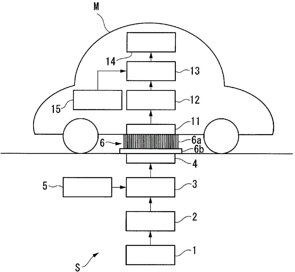
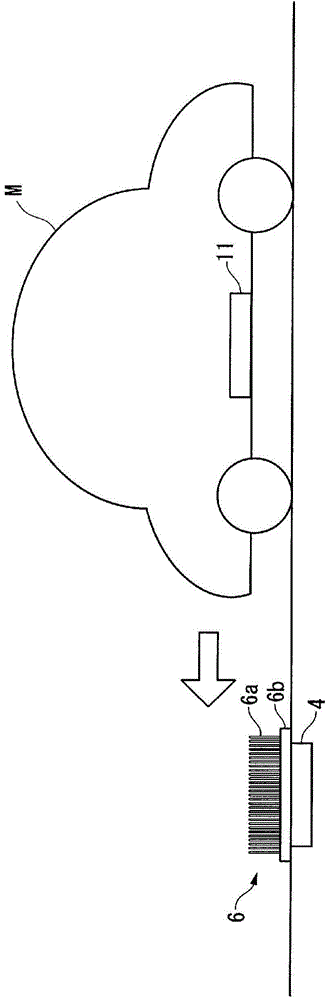
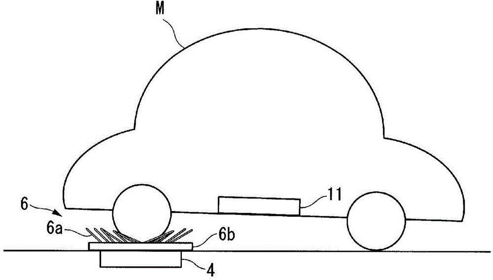
[0027] like figure 1 As shown, the contactless power supply system according to the first embodiment includes a ground power supply device S (power supply device) buried in the ground, and a vehicle M (mobile body) that receives power from the ground power supply device S.
[0028] Such a contactless power supply system supplies electric power from the ground power supply device S to the vehicle M in a contactless manner based on a magnetic field resonance method which is one of contactless power supply methods.
[0029] For example, the above-mentioned ground power supply device S is buried at a parking place at an intersection or a crossing, or at a parking place in a parking lot, and supplies power to vehicles M parked at these parking places without contact. like figure 1 As shown, such a ground power supply device S includes a power supply 1 , a rectifier circuit 2 , a power supply circuit 3 , a power supply coil 4 , a power supply control unit 5 , and a foreign object i...
no. 2 approach
[0047] Next, a contactless power supply system according to a second embodiment will be described.
[0048] The contactless power supply system of the second embodiment adds a foreign object detection unit 7 to the ground power supply device S of the first embodiment. Other components are the same as those of the first embodiment. Therefore, in the second embodiment, descriptions of the same components as those in the first embodiment are omitted.
[0049] The foreign matter detection unit 7 detects that a metal wrench or the like present on the foreign matter intrusion prevention unit 6 has a predetermined weight, that is, a weight that can bend the hair-like member 6a to the extent that a space equal to or greater than the size of the foreign matter can be invaded by the foreign matter. foreign matter, such as Figure 4A As shown, it consists of an optical fiber 7a and an optical measuring device 7b. In addition, the light measuring device 7b is a light emitting unit and ...
no. 3 approach
[0056] Next, a contactless power supply system according to a third embodiment will be described.
[0057] The contactless power supply system of the third embodiment adds a foreign object detection unit 8 to the ground power supply device S of the first embodiment. Other components are the same as those of the first embodiment. Therefore, in the third embodiment, descriptions of the same components as those in the first embodiment are omitted.
[0058] The foreign matter detection unit 8 detects a metal wrench or the like present on the foreign matter intrusion prevention unit 6, and has a predetermined weight, that is, the hair-shaped member 6a can create a space equal to or greater than the size of the foreign matter that can enter the foreign matter. foreign objects of the bending weight, such as Figure 4B As shown, it is composed of a linear member 8a and a strain detection part 8b.
[0059] The linear member 8a is made of an elastic material that allows a magnetic fi...
PUM
 Abstract
Description
Claims
Application Information
 - R&D
- Intellectual Property
- Life Sciences
- Materials
- Tech Scout
- Unparalleled Data Quality
- Higher Quality Content
- 60% Fewer Hallucinations
Browse by: Latest US Patents, China's latest patents, Technical Efficacy Thesaurus, Application Domain, Technology Topic, Popular Technical Reports.
© 2025 PatSnap. All rights reserved.Legal|Privacy policy|Modern Slavery Act Transparency Statement|Sitemap|About US| Contact US: help@patsnap.com