
Roll cooling device and method

A technology of segmented cooling and rolling, applied in the direction of rolling, length measuring device, metal rolling, etc., can solve the problems of lag, can not achieve instant effect, etc., to eliminate time lag, eliminate unfavorable thermal crown, and adjust in time. Effect

Active Publication Date: 2016-09-21
WISDRI ENG & RES INC LTD
View PDF7 Cites 0 Cited by
  • Summary
  • Abstract
  • Description
  • Claims
  • Application Information

AI Technical Summary

Problems solved by technology

At present, the segmental cooling mainly relies on the flatness signal fed back from the flatness roll at the exit of the rolling mill to determine the area where the emulsion needs to be sprayed on the roll body, and there is a long distance between the segmental cooling beam and the flatness roll, which leads to the segmentation There is always a time lag in the effect of cooling to improve the shape of the plate, and the immediate effect cannot be achieved

Method used


Image

  • Roll cooling device and method
  • Roll cooling device and method
  • Roll cooling device and method

Examples


Embodiment Construction

[0041] In order to make the object, technical solution and advantages of the present invention clearer, the present invention will be further described in detail below in conjunction with the accompanying drawings and embodiments. It should be understood that the specific embodiments described here are only used to explain the present invention, not to limit the present invention.

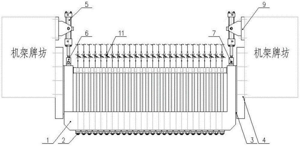
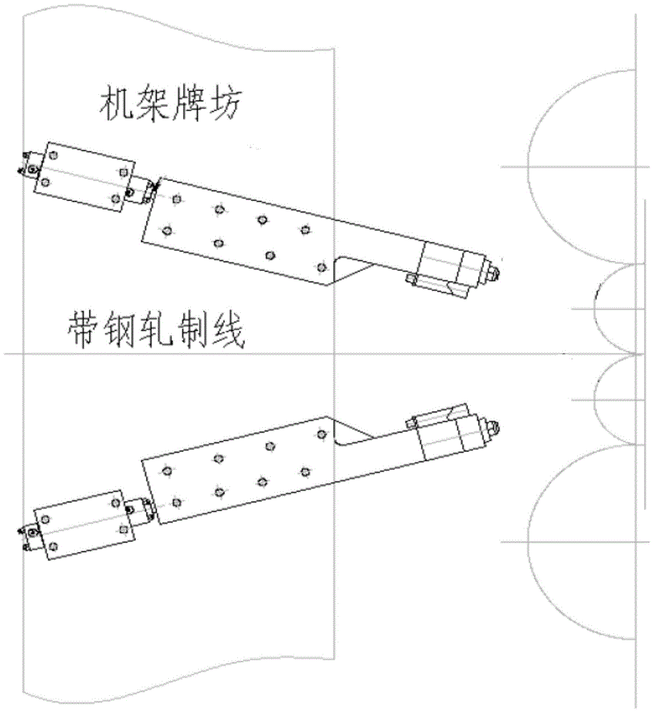
[0042] Such as Figure 1-Figure 2 As shown, there is provided a roll section cooling device, which is installed on the inlet side of the upper work roll and the lower work roll, and the device includes: a section cooling beam 1 and a section cooling controller;

[0043] A row of nozzles 2 facing the roll surface of the work roll is installed on the segmented cooling beam 1, each nozzle 2 is provided with a flow regulating valve 11, and a row of temperature sensors 10 corresponding to the nozzles 2 is installed on the segmented cooling beam 1 , the temperature sensor 10 is connected to the subsection...


PUM


Abstract

The invention discloses a sectional roller cooling device which comprises a sectional cooling beam and a sectional cooling controller, wherein a row of nozzles which face the surface of a working roller are mounted on the sectional cooling beam; a flow adjusting valve is arranged at each nozzle; a row of temperature sensors corresponding to the nozzles are arranged on the sectional cooling beam; the temperature sensors are connected with the sectional cooling controller; the temperature sensors are used for transmitting working roller surface temperature data detected at regular time to the sectional cooling controller; the sectional cooling controller controls the flow adjusting valve according to the received data; the sectional cooling controller is further connected with a plate shape roller and is used for receiving feedback information about whether the plate shape meets the requirements or not. By the adoption of the sectional roller cooling device, the time delay caused when the plate shape is improved through sectional cooling is eliminated, real-time adjustment on the thermal crown of the working roller is achieved, internal parameters can be modified according to signals fed back through the plate shape roller, and the purpose of precisely adjusting the plate shape is achieved.

Description

technical field [0001] The invention belongs to the technical field of cold-rolling metallurgical equipment, and in particular relates to a roll cooling device and method. Background technique [0002] In the cold rolling process, a large amount of heat will be generated due to the elastic-plastic deformation of the strip steel, and at the same time, due to the friction between the strip steel and the work roll, as well as the transmission friction between the work roll and the intermediate roll, heat will be generated during the rolling process. It will cause irregular expansion of the work roll, that is, the thermal crown of the work roll, which will lead to the change of the roll gap during the rolling process, and finally bring about the bad shape of the strip at the exit of the rolling mill. Conventional shape control methods such as tilting roll, bending roll and roll shifting are difficult to solve the irregular high-order shape problem caused by the thermal crown of ...

Claims


Application Information

Patent Timeline
Patent Type & Authority Patents(China)
IPC IPC(8): B21B27/10B21B37/32B21B37/74B21B38/00
Inventor 尉强严国平吴有生
Owner WISDRI ENG & RES INC LTD
Learn More