Pneumatic bidirectional clamping device for turning

A two-way clamping and turning belt technology, applied in turning equipment, positioning devices, clamping and other directions, can solve problems such as low efficiency and scrapped parts, achieve uniform contact surface, prevent deformation, and prevent product scrapping.

Inactive Publication Date: 2015-04-08
池州共康汽车零部件有限公司
View PDF0 Cites 3 Cited by
  • Summary
  • Abstract
  • Description
  • Claims
  • Application Information

AI Technical Summary

Problems solved by technology

[0003] The technical problem to be solved by the present invention is to provide a pneumatic two-way clamping device for turning belts to solve the problems of low efficiency of traditional clamping methods and scrapped parts

Method used


Image

  • Pneumatic bidirectional clamping device for turning

Examples


Embodiment Construction

[0022] In the following, numerous specific details are set forth in order to provide a thorough understanding of the concepts underlying the described embodiments. It will be apparent, however, to one skilled in the art that the described embodiments may be practiced without some or all of these specific details. In other instances, well known processing steps have not been described in detail.

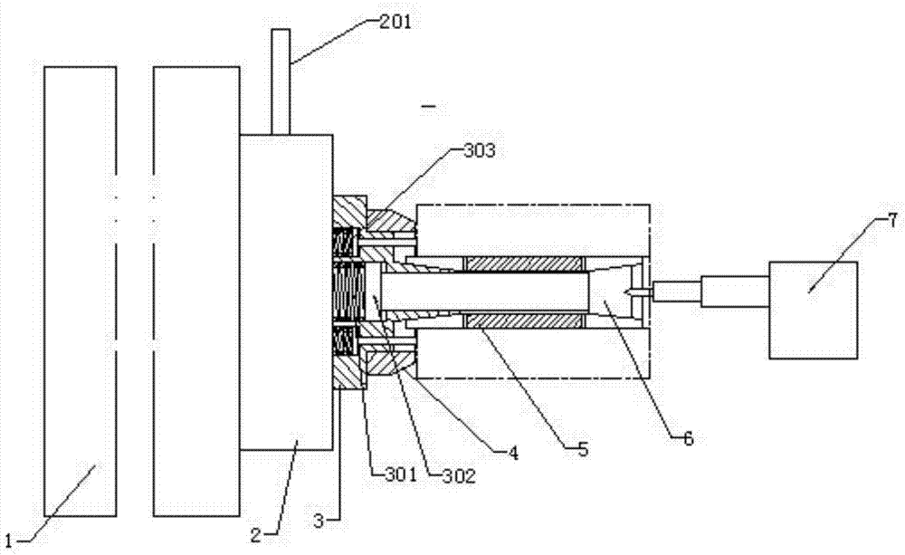
[0023] Such as figure 1 As shown, it includes main shaft 1, commutator 2, positioning center 3, positioning plate 4, two-way inner support sleeve 5, ejector rod 6, pneumatic tail top 7, commutator 2 is located at the center of the front end of main shaft 1, and the two are connected by threads , the positioning top 3 is located at the center of the front end of the commutator 2, the two are slidingly fitted and connected with threads, the positioning disc 4 is located at the center of the front end of the positioning top 3, the two are slipped and connected with threads, and the two-...


PUM


Abstract

The invention discloses a pneumatic bidirectional clamping device for turning. The pneumatic bidirectional clamping device for turning comprises a spindle, a reverser, a positioning centre, a positioning plate, a bidirectional inner support sleeve, an ejector rod and a pneumatic tail jack. The reverser is positioned at the center of the front end of the spindle, and the reverser and the spindle are in threaded connection; the positioning centre is positioned at the center of the front end of the reverser, and the positioning centre and the reverser are in slide fit and threaded connection; the positioning plate is positioned at the center of the front end of the positioning centre, and the positioning plate and the positioning centre are in slide fit and threaded connection; the bidirectional inner support sleeve is positioned at the center of the front end of the positioning centre, and the bidirectional inner support sleeve and the positioning centre are in slide fit and movable connection; the ejector rod is positioned at the inner center of the bidirectional inner support sleeve and is in threaded connection with the positioning centre; the pneumatic tail jack is positioned at the center of the front end of the ejector rod and is movably connected with a lathe guide rail. By the pneumatic bidirectional clamping device for turning, clamping efficiency is improved, product quality is guaranteed, and product scrappage is prevented.

Description

technical field [0001] The invention relates to a turning clamping device, in particular to a turning belt pneumatic bidirectional clamping device. Background technique [0002] Lathe machining is the foundation of the machining industry and is widely used in machining. For turning parts with a center hole and a long hole, the outer circle clamping method is to use the inner hole to clamp the workpiece. However, the inconsistent chamfering of the openings at both ends of this clamping method will cause the outer circle and the inner hole to be out of concentricity, resulting in scrapping the product, or resisting the inner holes at both ends, and this clamping method will cause the opening to be pinched and deformed. The product is scrapped, and the efficiency of these two clamping methods is low. In view of the above defects, it is necessary to design a turning belt pneumatic bidirectional clamping device. Contents of the invention [0003] The technical problem to be so...

Claims


Application Information

Patent Timeline
Patent Type & Authority Applications(China)
IPC IPC(8): B23B31/40B23B23/04
CPCB23B23/045B23Q3/00
Inventor 张启胜
Owner 池州共康汽车零部件有限公司
Why Eureka
Try Eureka