
Adjustable mold for tyre molding vulcanizing machine

A technology of flexible mold and tire forming, which is applied to household appliances, other household appliances, tires, etc., can solve the problems of reduced utilization rate of workpieces, troublesome operation, bumps, etc., so as to achieve complete and undamaged joints, reasonable structural design, and utilization rate. high effect

Inactive Publication Date: 2015-04-08
山东力创模具股份有限公司
View PDF6 Cites 2 Cited by
  • Summary
  • Abstract
  • Description
  • Claims
  • Application Information

AI Technical Summary

Problems solved by technology

[0003] The existing flexible mold has the following defects in use: first, the lower steel ring is directly fixed to the lower chuck, and when vulcanizing tires of the same size and different specifications, the lower steel ring needs to be removed from the lower chuck, and then the lower steel ring of the corresponding specification is selected. The ring and the lower chuck are fixed for use, and the lower side plate must be replaced accordingly. The operation is cumbersome, time-consuming and laborious, and the utilization rate of the workpiece is reduced; secondly, during the process of vulcanization and bodilessing, the lower steel ring and the lower chuck are continuously raised and lowered with the central mechanism. It will cause wear and scratches at the joint between the lower steel ring and the lower side plate, and the vulcanized tire will have defects such as rubber edges or bulges here, and the appearance quality of the tire will be reduced
In summary, the existing design using the structure directly fixed between the lower steel ring and the lower chuck cannot meet the requirements for tire quality and the utilization rate of workpieces

Method used


Image

  • Adjustable mold for tyre molding vulcanizing machine
  • Adjustable mold for tyre molding vulcanizing machine

Examples


Embodiment Construction

[0011] In order to clearly illustrate the technical features of this solution, the present invention will be described in detail below through specific implementation modes and in conjunction with the accompanying drawings.

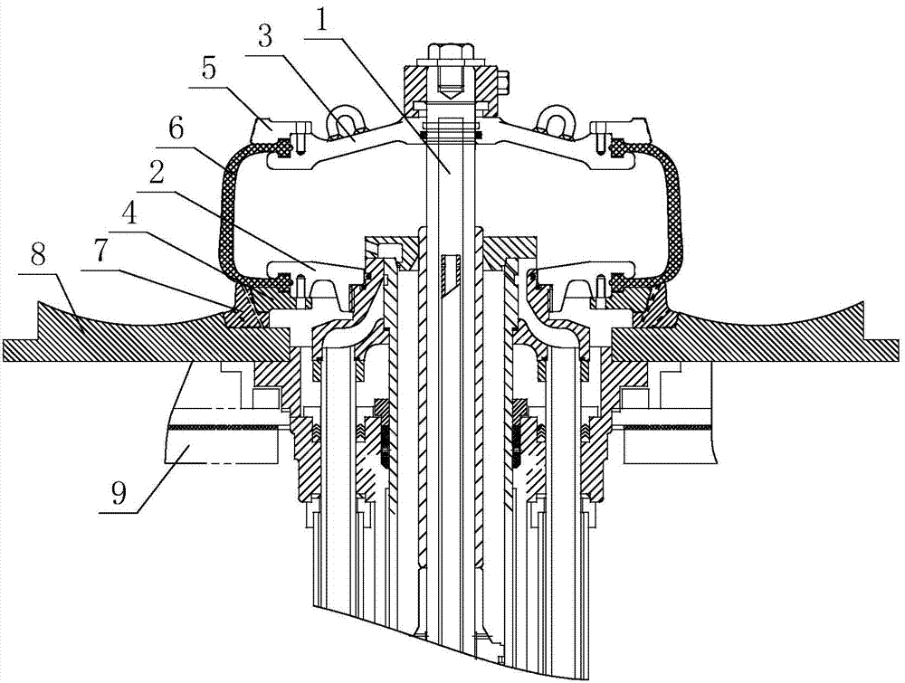
[0012] Such as figure 2 As shown, a movable mold for a tire molding vulcanizer includes a lower chuck 2 and an upper chuck 3 respectively connected to the central mechanism 1 of the vulcanizer, and the lower chuck 2 and the upper chuck 3 are connected to the transition plate 4 and the transition plate 3 through bolts respectively. The upper steel ring 5 is fixedly connected, the lower chuck 2 and the transition plate 4 clamp the bottom edge of the capsule 6, the upper chuck 3 and the upper steel ring 5 clamp the top edge of the capsule 6, and a lower clamp is provided outside the transition plate 4. The steel ring 7 and the bottom edge of the transition plate 4 are matched with the lower steel ring 7, and the lower steel ring 7 is fixedly installed on th...


PUM


Abstract

The invention provides an adjustable mold for a tyre molding vulcanizing machine. The adjustable mold comprises a lower chuck and an upper chuck, which are connected with a vulcanizing machine central mechanism; the lower chuck and the upper chuck are fixedly connected with a transition disc and an upper steel ring by bolts respectively; the lower chuck and the transition disc are used for clamping a clamping edge part of the bottom of a capsule; the clamping edge part at the top of the capsule is clamped by the upper chuck and the upper steel ring; a lower steel ring is arranged on the outer side of the transition disc; the edge of the bottom of the transition disc is matched with and in butt joint with the lower steel ring; and the lower steel ring is fixedly mounted on a lower side plate. The lower chuck is connected with the lower steel ring by the transition disc; the lower steel ring is directly and fixedly mounted on the lower side plate; the transition disc and the lower chuck are hoisted along with the vulcanizing machine central mechanism; firstly, the transition disc does not need to be detached when tyres with the same size and different specifications are vulcanized, and only the lower steel ring and the lower side plate need to be replaced; the operation is simple, the time and labor are saved and the utilization rate of workpieces is high; and secondly, the matched part of the lower steel ring and the lower side plate is intact and lossless, and the vulcanized tyres do not have the defects of rubber edges or bulges so that the quality of the tyres is guaranteed.

Description

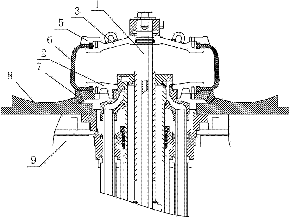
Technical field: [0001] The invention relates to a movable mold for a tire molding vulcanizer. Background technique: [0002] Existing tire molding and vulcanizing machine uses movable mold, its structure is as follows figure 1 As shown, it includes the lower chuck 2 and the upper chuck 3 which are respectively connected with the central mechanism 1 of the vulcanizing machine. The plate 2 and the lower steel ring 7 clamp the edge of the bottom of the capsule 6, the upper chuck 3 and the upper steel ring 5 clamp the edge of the top of the capsule 6, the lower steel ring 7 is movably placed on the lower side plate 8, and the lower steel ring 7 The bottom is mated with the lower side plate 8, and the lower side plate 8 is installed on the base table panel 9 again. After the tire is vulcanized, the water cylinder of the central mechanism 1 of the vulcanizing machine is extended, the superheated water in the capsule 6 is discharged, the capsule 6 is stretched, and then the lowe...

Claims


Application Information

Patent Timeline
IPC IPC(8): B29C33/30B29C33/44B29C35/02B29L30/00
Inventor 裴升明刘杰
Owner 山东力创模具股份有限公司
Learn More