
Dielectric lens processing method and dielectric lens prepared by utilizing same

A technology of dielectric lens and processing method, applied in electrical components, antennas and other directions, can solve the problems of lens affecting performance, etc., and achieve the effect of reducing processing cost, excellent performance, and improving processing accuracy and technical performance

Inactive Publication Date: 2015-04-08
HUBEI SANJIANG SPACE XIANFENG ELECTRONICS&INFORMATION CO LTD
View PDF3 Cites 2 Cited by
  • Summary
  • Abstract
  • Description
  • Claims
  • Application Information

AI Technical Summary

Problems solved by technology

[0005] Aiming at the above defects or improvement needs of the prior art, the present invention provides a method for processing a dielectric lens and the products prepared by the method. The dielectric lens is divided into two parts and injected separately, and the injection molding of the latter part is completed. The first part is put into the injection mold, so that a dielectric lens with good consistency, low cost and no bubbles can be obtained, which solves the problem that the bubbles in the lens affect its performance due to the unevenness of the impedance matching branch in the current lens injection molding

Method used


Image

  • Dielectric lens processing method and dielectric lens prepared by utilizing same
  • Dielectric lens processing method and dielectric lens prepared by utilizing same
  • Dielectric lens processing method and dielectric lens prepared by utilizing same

Examples


Embodiment Construction

[0020] In order to make the object, technical solution and advantages of the present invention clearer, the present invention will be further described in detail below in conjunction with the accompanying drawings and embodiments. It should be understood that the specific embodiments described here are only used to explain the present invention, not to limit the present invention. In addition, the technical features involved in the various embodiments of the present invention described below can be combined with each other as long as they do not constitute a conflict with each other.

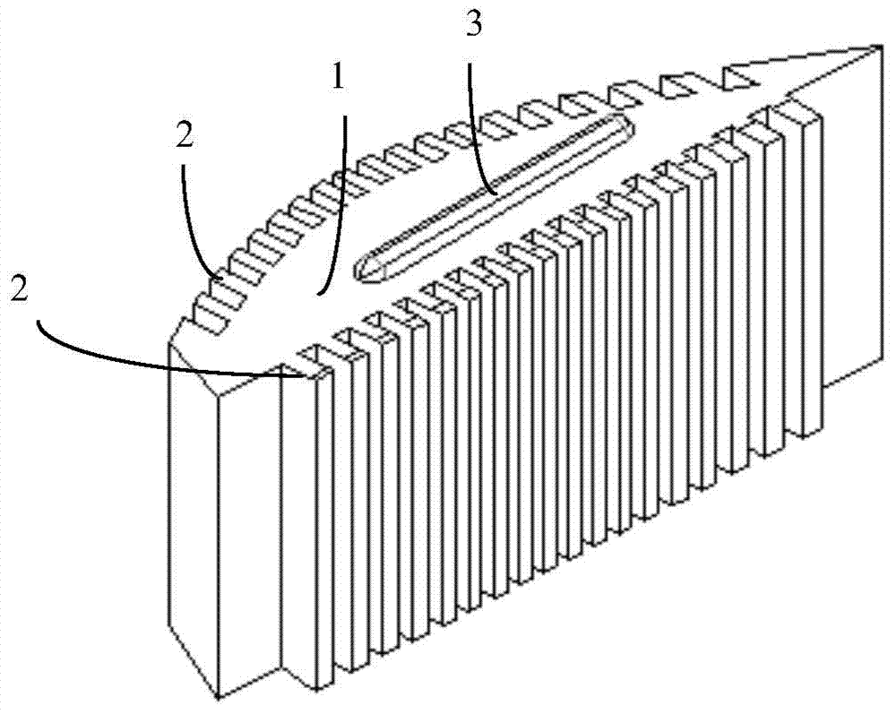
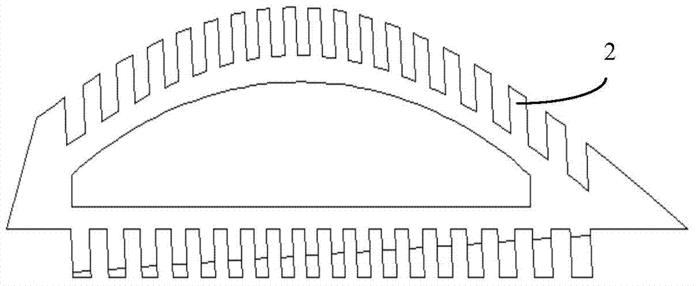
[0021] Such as figure 1 As shown, the dielectric lens includes a dielectric lens impedance matching branch 2, a dielectric lens main body 1, and bosses arranged on both sides of the main body.

[0022] According to the injection molding processing method of the dielectric lens constructed in this embodiment, when the above dielectric lens is injection molded, the lens is divided into two parts ...


PUM


Abstract

The invention discloses a dielectric lens processing method. The method comprises the following steps: dividing a dielectric lens into a first injection molding part and a second injection molding part, wherein the first injection molding part is positioned at the periphery of the lens and comprises an impedance matching branch knot, and a cavity is formed inside the first injection molding part, the second injection molding part can be positioned in the cavity of the first injection molding part and is matched with the first injection molding part; performing injection molding on the second injection molding part, adding the molded second injection molding part in a cavity which corresponds to an injection mold of the first injection molding part; and performing injection molding so as to fuse the dielectric surfaces of the two parts together, thus forming the dielectric lens wholly. The invention also discloses a dielectric lens prepared by utilizing the method and application thereof. According to the method disclosed by the invention, the dielectric lens with high consistency and low cost and without bubbles can be obtained, and the problem that the lens has bubbles so as to influence the performance due to non-uniform impedance matching branch knots in the conventional lens injection molding is solved.

Description

technical field [0001] The invention belongs to the field of microwave communication, and in particular relates to a processing method for a dielectric lens of a horn antenna, which is suitable for a dielectric horn antenna. Background technique [0002] Dielectric lens is mainly composed of lens body, impedance matching branch and boss. Among them, the main body of the lens is a uniform entity, and the whole is an arc-shaped plate structure, in which a plurality of grooves are opened on the curved surface part and the opposite planar part, so that a plurality of teeth are formed on the surface as impedance matching branches . The boss is provided by protruding out of the planes on both sides of the plate body parallel to each other. Generally speaking, the impedance matching stubs are mainly non-uniform matching stubs, that is, the thickness of each tooth will be different. [0003] At this stage, most of the dielectric lenses of horn antennas are made of foamed polyethy...

Claims


Application Information

Patent Timeline
IPC IPC(8): B29C45/00B29C45/14H01Q15/08
CPCB29C45/14467H01Q15/08
Inventor 姜典彬李坤军
Owner HUBEI SANJIANG SPACE XIANFENG ELECTRONICS&INFORMATION CO LTD
Learn More