Sucker paper receiving device

A suction cup and paper technology, which is applied in stacking receiving devices, transportation and packaging, and sending objects, etc., can solve the problems of limited function, inability to use flat paper, etc., and achieve the effect of neat stacking and precise displacement

Active Publication Date: 2015-04-08
NANTONG SITONG FORESTRY MACHINE MFG INSTALLATION
View PDF11 Cites 12 Cited by
  • Summary
  • Abstract
  • Description
  • Claims
  • Application Information

AI Technical Summary

Problems solved by technology

But it can only be used for rolled paper, it cannot be used for laying paper, the effect is limited

Method used


Image

  • Sucker paper receiving device

Examples


Embodiment Construction

[0026] The present invention is described in further detail now in conjunction with accompanying drawing. These drawings are all simplified schematic diagrams, which only illustrate the basic structure of the present invention in a schematic manner, so they only show the configurations related to the present invention.

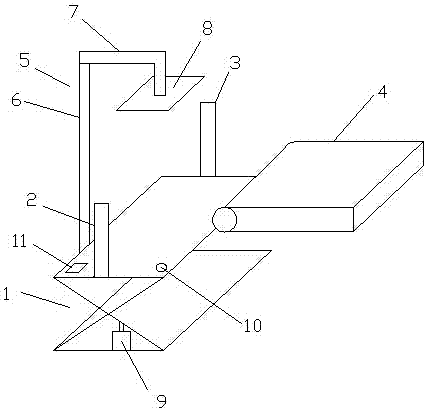
[0027] Such as figure 1 As shown, a suction cup paper receiving device includes a frame 1, and the frame 1 is a liftable frame; a pair of symmetrically arranged limit rods are arranged on the longitudinal axis of the frame table, which is divided into a first longitudinal limit Position bar 2 and the second longitudinal limit bar 3; The connecting line of the first longitudinal limit bar 2 and the second longitudinal limit bar 3 is perpendicular to the direction of paper conveyance, and is far away from the paper conveyor belt 4 on the frame table. On one side, at least one mechanical arm 5 is provided, and the mechanical arm 5 includes a vertically arranged ...


PUM


Abstract

The invention discloses a sucker paper receiving device which comprises a liftable frame. A pair of symmetrical limit rods is disposed on the longitudinal axis of the table board of the frame. The limit rods include a first longitudinal limit rod and a second longitudinal limit rod. The connecting line of the first longitudinal limit rod and the second longitudinal limit rod is vertical to a paper conveying direction. At least one mechanical arm is disposed on one side, away from a paper conveying belt, of the table board of the frame. Each mechanical arm comprises a vertical lifting rod, an inverted L-shaped telescopic rod vertically disposed at the top end of the lifting rod, and a sucker disposed at the free end of the telescopic rod. Compared with the prior art, the sucker paper receiving device has the advantages that paper can be stacked neatly, and next-step operation is benefited.

Description

technical field [0001] The invention relates to a sucker paper splicing device. Background technique [0002] At present, the common paper splicers in the market are divided into horizontal and vertical. The horizontal paper splicer and the horizontal uncoiler are integrated and cannot be used separately; although the vertical paper splicer is an independent stand-alone machine, the single machine splicing function is not perfect. They all have their own shortcomings. [0003] The paper splicing mechanism of the paper cutter disclosed in Chinese patent 201110092663.7 includes a servo motor, a paper splicing plate and a supporting channel steel. The servo motor is installed on the supporting channel steel. It is connected to the servo motor through a belt, and the paper receiving plate is connected to the belt through a mounting plate; There is a slide block that can slide on the guide rail, the installation plate is installed on the slide block; the paper receiving seat is...

Claims


Application Information

Patent Timeline
Patent Type & Authority Applications(China)
IPC IPC(8): B65H31/04B65H31/34B65H43/06
Inventor 陆新明王建清李金炎朱玲
Owner NANTONG SITONG FORESTRY MACHINE MFG INSTALLATION
Why Eureka
Try Eureka