Supercharge Your Innovation With Domain-Expert AI Agents!

Narrow-foundation-tower single-pile pier-type self-stabilized foundation for power transmission line

A technology for power transmission lines and single-pile foundations, which is applied in infrastructure engineering, sheet pile walls, buildings, etc., can solve the problems of high geological conditions, great influence of municipal facilities, uneconomical engineering application, etc., to shorten the construction period, Strong resistance to horizontal displacement and the effect of reducing the footprint

Active Publication Date: 2015-04-08
STATE GRID CORP OF CHINA +1
View PDF9 Cites 4 Cited by
  • Summary
  • Abstract
  • Description
  • Claims
  • Application Information

AI Technical Summary

Problems solved by technology

Large excavation combined foundation is a kind of natural foundation, but it needs large-scale excavation. Construction in urban areas has a great impact on municipal facilities, and has high requirements on geological conditions, so it is rarely used. Generally, pile foundations are mainly used; ordinary cast-in-place piles The foundation is to arrange pile foundations separately under the four tower legs of the narrow foundation tower. The mutually independent foundations must satisfy both the uplift calculation and the downforce calculation. The configured foundation is relatively large
Especially for linear towers with small loads, it is not necessary in terms of bearing capacity requirements, but in order to meet the needs of structure and construction, a larger pile diameter has to be designed, which is very uneconomical in engineering applications; The pipeline network is densely covered, and the four-legged single pile foundation in complex areas often cannot be arranged, and the route is often changed to bypass or relocate underground pipelines. This often results in a large construction cost due to an obstacle

Method used


Image

  • Narrow-foundation-tower single-pile pier-type self-stabilized foundation for power transmission line
  • Narrow-foundation-tower single-pile pier-type self-stabilized foundation for power transmission line
  • Narrow-foundation-tower single-pile pier-type self-stabilized foundation for power transmission line

Examples


Embodiment Construction

[0032] The specific implementation manners of the present invention will be further described in detail below in conjunction with the accompanying drawings.

[0033] In order to thoroughly understand the embodiments of the present invention, the detailed structure will be set forth in the following description. Obviously, the practice of the embodiments of the invention is not limited to specific details familiar to those skilled in the art. Preferred embodiments of the present invention are described in detail below, however, the present invention may have other embodiments besides these detailed descriptions.

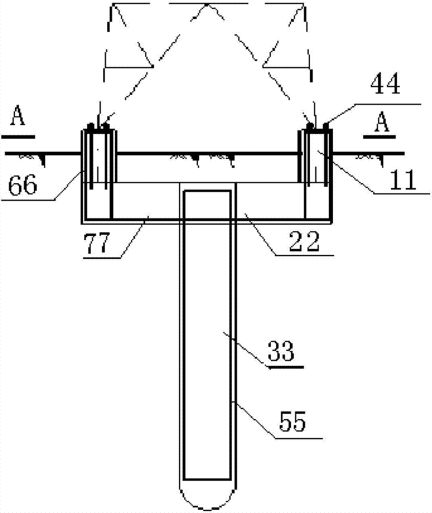
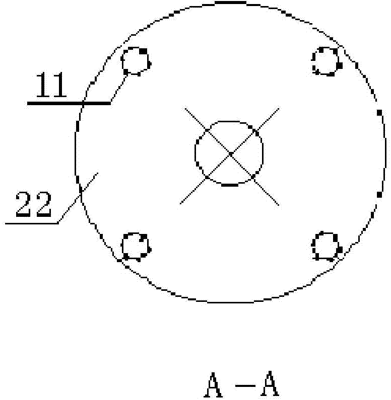
[0034] refer to figure 1 with figure 2 , figure 1 It is a structural schematic diagram of a single-pile pier type self-stabilizing foundation of a transmission line narrow base tower of the present invention; figure 2 for figure 1 A-A sectional view in . The single-pile self-stabilizing foundation for transmission line narrow foundation towers shown in the fig...


PUM

PropertyMeasurementUnit
Diameteraaaaaaaaaa
Diameteraaaaaaaaaa
Thicknessaaaaaaaaaa

Abstract

The invention discloses a narrow-foundation-tower single-pile pier-type self-stabilized foundation for a power transmission line. The narrow-foundation-tower single-pile pier-type self-stabilized foundation for the power transmission line comprises a single-pile foundation, a pier platform and small upright columns (11), wherein the upper end of a single pile is inserted into the center of the pier platform; the small upright columns (11) are positioned on the upper end surface of the pier platform; four independent tower leg upright columns of a narrow foundation tower are buried onto one pier platform; the pier platform is supported by the single-pile foundation buried inside soil; acting forces of four tower legs which are essentially not related to one another act on one point, and through mutual counteraction, a self-balancing aim is achieved; the conventional four independent foundations are changed into one self-stabilized single-pile foundation, so that the occupied area is obviously reduced, the cost of the foundation is reduced; the construction technology is simple, the construction period is significantly shortened, and the narrow-foundation-tower single-pile pier-type self-stabilized foundation is more safe and convenient.

Description

technical field [0001] The invention relates to a self-stabilizing foundation, in particular to a single-pile pier type self-stabilizing foundation of a narrow base tower of a power transmission line. Background technique [0002] At present, there are more and more high-voltage lines in urban planning areas, and the line corridors are becoming more and more tense. Ordinary iron towers cannot meet the requirements of urban high-voltage lines occupying less land. Generally, three methods are used to reduce urban land use, namely, steel pipe poles, cable buried tube and narrow base tower. [0003] The service conditions of steel pipe poles are higher than those of iron towers, and large machinery is required for erection, which has high requirements on the construction site environment and relatively inconvenient maintenance in the later stage; the investment in buried pipes for cables is large, and is too limited by factors such as underground pipelines and rivers, and later ...

Claims


Application Information

Patent Timeline
IPC IPC(8): E02D27/42E02D27/12
CPCE02D5/38E02D27/14E02D27/42E02D2300/002E02D2300/0034
Inventor 鲁先龙郑卫锋满银苏荣臻
Owner STATE GRID CORP OF CHINA
Features
  • R&D
  • Intellectual Property
  • Life Sciences
  • Materials
  • Tech Scout
  • Unparalleled Data Quality
  • Higher Quality Content
  • 60% Fewer Hallucinations
Learn More