Piston device having volume cavity in top

A technology of volume cavity and piston, which is applied in the direction of engine control, machine/engine, mechanical equipment, etc., can solve the problems such as self-regulation cannot be realized, and achieve the effect of simple structure, reasonable design and high combustion efficiency

Inactive Publication Date: 2015-04-08
韦晓晖
View PDF0 Cites 0 Cited by
  • Summary
  • Abstract
  • Description
  • Claims
  • Application Information

AI Technical Summary

Problems solved by technology

[0003] After searching the existing literature, it is found that the patent application number is 20092014360.5, and the name is a patented technology of a mechanism that can change the compression ratio of the engine. A variable compression ratio mechanism is proposed to make the combustion efficiency higher, but its compression ratio changes. Requires artificial control, cannot achieve self-regulation

Method used


Image

  • Piston device having volume cavity in top
  • Piston device having volume cavity in top
  • Piston device having volume cavity in top

Examples


Embodiment

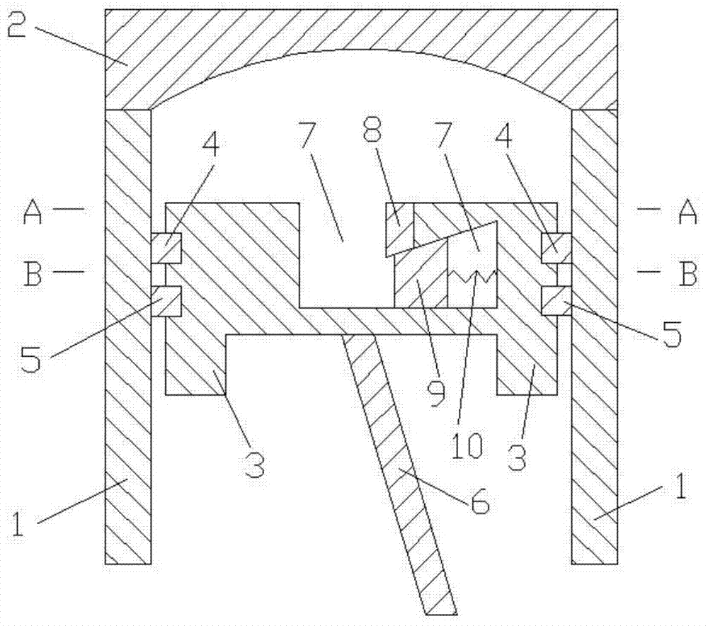
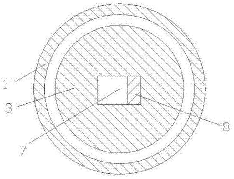
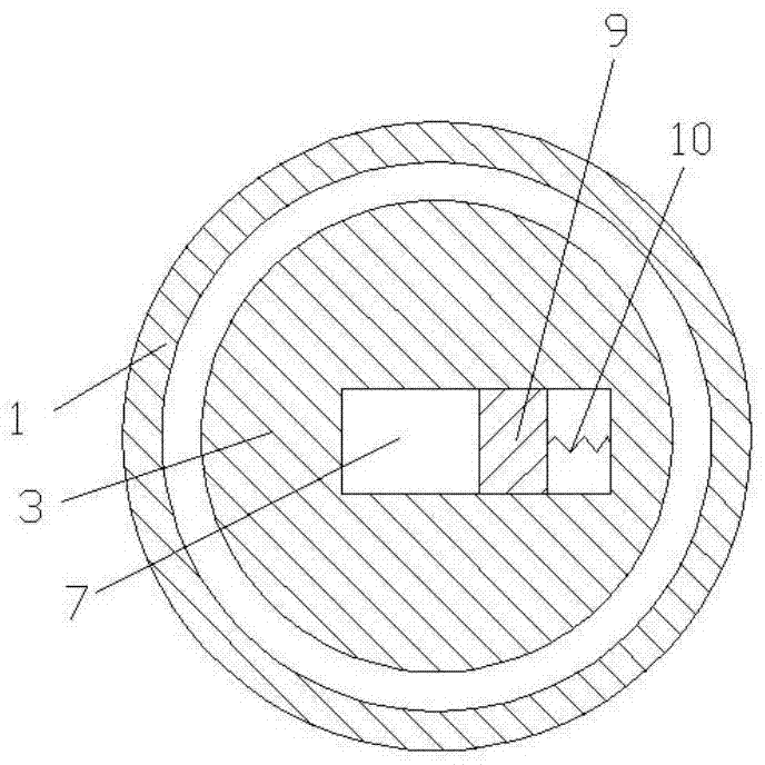
[0013] Examples of the present invention are Figure 1 to Figure 3 As shown, the present invention includes a cylinder 1, a cylinder head 2, a piston 3, a first piston ring 4, a second piston ring 5, a connecting rod 6, a volume chamber 7, a first moving body 8, a second moving body 9 and a spring 10 , the cylinder head 2 is arranged on the upper end of the cylinder 1, the piston 3 is arranged in the cylinder 1, the cylinder 1, the cylinder head 2, and the piston 3 together form a combustion chamber, and the first piston ring 4 and the second piston ring 5 are arranged on the piston 3 The top of the connecting rod 6 is connected with the piston 3, the volume cavity 7 is arranged on the top of the piston 3, the volume cavity 7 is divided into left and right parts, the first moving body 8 and the second moving body 9 are arranged in the volume cavity 7 , the first moving body 8 is arranged above the second moving body 9, the lower end surface of the first moving body 8, the uppe...


PUM


Abstract

The invention discloses a piston device having a volume cavity in the top, and belongs to the technical field of internal combustion engines. The piston device comprises a cylinder, a cylinder cover, a piston, a piston ring, a connecting rod, the volume cavity, a spring and mobile bodies, wherein the volume cavity is formed in the top of the piston, and is divided into left and right two parts; first and second mobile bodies are both arranged in the volume cavity; the first mobile body is arranged above the second mobile body; the lower end surface of the first mobile body, the upper end surface of the second mobile body and the upper end surface of the right part of the volume cavity are all slope structures; and the lower end surface of the first mobile body and the upper end surface of the second mobile body are in sealing contact. Under the working condition of high speed, when the pressure is the highest and the combustion pressure is higher in a combustion chamber, the second mobile body moves to the right side, the first mobile body downwards moves, and the volume of the combustion chamber is increased; and under the working condition of low speed, when the pressure is the highest and the combustion pressure is lower in the combustion chamber, the second mobile body moves to the left side, the first mobile body upwards moves, and the volume of the combustion chamber is decreased. The piston device is reasonable in structure and simple in design, and is suitable for optimal design of engine pistons.

Description

technical field [0001] The invention belongs to a compression ratio design device in the technical field of internal combustion engines, in particular to a piston device with a volume cavity at the top. Background technique [0002] The compression ratio refers to the degree to which the engine mixture is compressed, using the ratio of the total volume of the cylinder before compression to the volume of the cylinder after compression (that is, the volume of the combustion chamber). At present, the vast majority of automobiles use the so-called 'reciprocating engine'. Simply put, in the engine cylinder, there is a piston that reciprocates in a straight line and continues to cycle. There is a certain range of motion in the stroke. As far as a certain cylinder of the engine is concerned, when the stroke of the piston reaches the lowest point, the position at this time is called the bottom dead center. The volume formed by the entire cylinder including the combustion chamber is...

Claims


Application Information

Patent Timeline
Patent Type & Authority Applications(China)
IPC IPC(8): F02D15/02
Inventor 韦晓晖
Owner 韦晓晖
Why Eureka
Try Eureka