
A variable compression ratio rotary engine with reciprocating arc motion

A rotary engine, circular motion technology, applied in combustion engine, engine control, machine/engine, etc., can solve the problems of serious pollution, low thermal efficiency, hindering the promotion of triangular rotary engine, etc.

Inactive Publication Date: 2019-02-19
SHANDONG UNIV OF TECH
View PDF4 Cites 0 Cited by
  • Summary
  • Abstract
  • Description
  • Claims
  • Application Information

AI Technical Summary

Problems solved by technology

[0004] Due to the lack of high compression ratio of the triangular rotor engine, the combustion is insufficient, the fuel consumption is high, the pollution is serious, and the lubrication condition of the triangular rotor engine is poor, the mechanical wear is serious, and the cylinder is not heated uniformly, which hinders the popularization of the triangular rotor engine
[0005] At present, most turbocharged engines have a fixed compression ratio when they leave the factory, and the turbine blows excess air into the cylinder forcibly. In order to prevent this phenomenon, a lower compression ratio is basically used, but a low compression ratio means lower thermal efficiency. When the turbo is not fully involved (that is, when the engine speed is low), the combustion efficiency is very low.

Method used


Image

  • A variable compression ratio rotary engine with reciprocating arc motion
  • A variable compression ratio rotary engine with reciprocating arc motion
  • A variable compression ratio rotary engine with reciprocating arc motion

Examples


no. 1 example

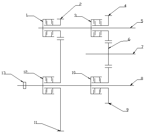
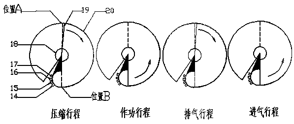
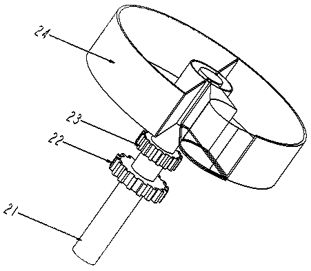
[0031] Such as figure 1 , 2 , 3, a kind of reciprocating arc motion variable compression ratio rotary engine of the present invention comprises: vehicle-mounted ECU, cylinder block 20, rotor 19, arc-shaped plate 18 rigidly connected with rotor 19, fuel injection device 17 , ignition device 16, intake valve 15, exhaust valve 14, angular displacement sensor 13, fourth clutch 12, fifth gear 11, third clutch 10, fourth gear 9, engine shaft 8, reversing shaft 7, the first Three gears 6, output shaft 5, second gear 4, second clutch 3, first gear 2, first clutch 1. Wherein the rotor 19 is rigidly connected with the engine shaft 8, the arc plate 18 can rotate together with the rotor 19, and the angular displacement sensor 13 is installed on the engine shaft 8, and the arc plate 18 has three mutual contact positions with the cylinder block 20 when rotating, each There is a sealing strip at the first position, the fifth gear 11 and the fourth gear 9 are sleeved on the engine shaft 8 w...

no. 2 example

[0038] In order to speed up the separation and coupling speed of each clutch, the first clutch 1, the second clutch 3, the third clutch 10, and the fourth clutch 12 all adopt electromagnetic rheological devices. By giving the first clutch 1, the second clutch 3, and the third Different control voltages of the clutch 10 and the fourth clutch 12 control the disengagement or engagement of the first clutch 1 , the second clutch 3 , the third clutch 10 and the fourth clutch 12 .

[0039] Finally, the method for realizing the variable compression ratio of the engine is explained:

[0040] The angular displacement sensor can continuously detect the rotation angle of the rotor relative to the position B. The vehicle-mounted ECU detects the rotation angle of the rotor 19 relative to the position B in real time through the angular displacement sensor 13. When the angle reaches the angle value set by the system, the vehicle-mounted ECU controls the hydraulic pressure. The system leads to...


PUM


Abstract

A variable compression ratio rotor engine with reciprocating circular arc motion belongs to the field of mechatronics and includes a wet clutch, an angular displacement sensor, a transmission gear, a reversing shaft and the like. It is characterized in that: the angular displacement sensor can continuously detect the rotation angle of the rotor relative to position B, and when the on-board ECU judges that the angle reaches the angle set by the system, it controls the hydraulic system to connect or disconnect each wet clutch, and switches the transmission route, so that The reciprocating arc motion of the rotor is converted into the one-way circular motion of the output shaft. At the same time, the on-board ECU can judge whether it is necessary to change the engine compression ratio according to the driving conditions of the vehicle. When the compression ratio needs to be changed, the on-board ECU changes it according to the model preset by the vehicle. The maximum angle value that the rotor can rotate currently set by the system makes the maximum angle that the engine rotor can rotate different, the total volume of the cylinder changes, but the volume of the combustion chamber remains unchanged, so that the compression ratio is variable. The invention has the advantages of realizing variable compression ratio of the rotary engine, wide range of compression ratio and large maximum compression ratio.

Description

technical field [0001] The invention relates to a variable compression ratio rotor engine with reciprocating arc motion, which belongs to the field of electromechanical integration. Background technique [0002] Compared with traditional reciprocating engines, rotary engines rely on the expansion force generated by the combustion of air-fuel mixture to obtain rotational force. The difference between the two engines lies in the way the expansion force is used. The traditional reciprocating engine converts the expansion force into linear motion through the piston and cylinder, and then converts it into the circular motion of the engine output shaft through the crank linkage; the rotary engine directly converts the expansion force into the circumference of the engine output shaft through a specific mechanical structure sports. [0003] The traditional reciprocating engine inevitably causes mechanical energy loss when converting linear motion into circular motion, while the rot...

Claims


Application Information

Patent Timeline
Patent Type & Authority Patents(China)
IPC IPC(8): F02B53/02F02D15/04
CPCF02B53/02F02D15/04Y02T10/12
Inventor 沈玉凤徐国辉邹宏骏吕少文冯晓志张为春
Owner SHANDONG UNIV OF TECH
Learn More