Rigid-flexible composite filtering gear

A rigid-flexible composite, gear technology, applied in the direction of gear transmission, belt/chain/gear, components with teeth, etc., can solve the problems of increasing the vibration of the gear transmission mechanism, noise, lubrication failure, affecting the life of the gear, etc. Achieve the effect of enhancing anti-vibration ability, high service life and wide application range

Inactive Publication Date: 2015-04-08
CHONGQING UNIV
View PDF9 Cites 12 Cited by
  • Summary
  • Abstract
  • Description
  • Claims
  • Application Information

AI Technical Summary

Problems solved by technology

Although the backlash is small, the transmission precision is high, but the gears are prone to various interferences when meshing
The impact of meshing and meshing when the gear teeth mesh, and the loss of parts during operation will increase the vibration and noise of the gear transmission mechanism during operation, and affect the life of the gear.
Especially under extreme working conditions and special environments (such as vibration, high and low temperature alternation), the volume thermal expansion of gears and the harsh external mechanical environment will cause nonlinear coupling vibration of the drive mechanism and lead to tooth profile interference, lubrication failure, and even It is the phenomenon of "stuck" or "stuck" between teeth, which affects the reliability of gear transmission
On the other hand, the motor is the source of the transmission device. The mechanical energy generated by the motor is in a state of high speed and low torque. When it is output through the reducer, it becomes a state of low speed and high torque. During this period, due to the manufacturing and assembly errors of the parts themselves, the gear meshing impact cannot be achieved. Avoid fluctuations in the transmission of torque and speed

Method used


Image

  • Rigid-flexible composite filtering gear
  • Rigid-flexible composite filtering gear
  • Rigid-flexible composite filtering gear

Examples


no. 1 example

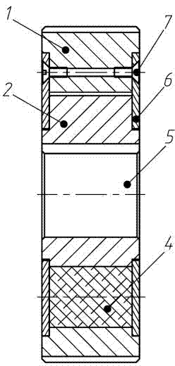
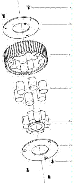
[0031] Such as figure 1 As shown, it is a structural schematic diagram of an embodiment of the rigid-flexible compound filtering external gear of the present invention. The rigid-flexible compound filter external gear of this embodiment includes an external gear 1 and a hub 2 fitted in the external gear 1 with clearance fit. The outer peripheral wall of the external gear 1 is provided with gear teeth I3, and the external gear 1 and the hub 2 Elastomer filling holes I are evenly distributed in the ring, and high damping elastomer I4 is arranged in the elastomer filling hole I. Specifically, the inner hole wall of the outer ring gear 1 is provided with an arc-shaped groove I, and the hub 2 An arc-shaped groove II is provided on the peripheral wall of the body, and the arc-shaped groove I and the arc-shaped groove II cooperate to form the elastomer filling hole I. The center of the hub 2 is provided with a central through hole 5, which can be easily matched with the gear shaft. ...

no. 2 example

[0037] Such as Figure 4 As shown, it is a structural schematic diagram of an embodiment of the rigid-flexible compound filtering internal gear of the present invention. The rigid-flexible compound filtering internal gear of this embodiment includes an internal ring gear 8 and a tooth seat 9 fitted outside the internal ring gear 8 with clearance fit. The inner peripheral wall of the internal ring gear 8 is provided with gear teeth II10, and the internal ring gear 8 and Elastomer filling holes II are evenly distributed in a ring between the gear seats 9, and high damping elastomer II11 is arranged in the elastomer filling holes II. Specifically, an arc-shaped groove III is provided on the wall of the inner hole of the inner ring gear 8, and an arc-shaped groove IV is provided on the outer peripheral wall of the tooth seat 9. The arc-shaped groove III and the arc-shaped groove IV cooperate to form an elastic body. Fill hole II. The size of the fit gap between the inner ring ge...

no. 3 example

[0042] Such as Figure 5 As shown, it is a structural schematic diagram of an embodiment of the rigid-flexible compound filtering gear meshing pair of the present invention. The rigid-flexible compound filter gear meshing pair in this embodiment includes two gears meshing with each other. Among the two gears in this embodiment, one is an external gear 14, and the other is an internal gear 15, and the external gear 14 adopts a rigid-flexible compound filter external gear as described in the first embodiment, and the internal gear is an ordinary gear. An eccentric shaft 16 is installed in the central through hole of the hub 2 of the internal gear 15 of this embodiment, a bearing 17 is provided between the eccentric shaft 16 and the central through hole, and an eccentric distance e is provided between the external gear 14 and the internal gear 15 . Further, the axes of the two gears are parallel to or intersect each other, and the axes of the two gears in this embodiment are par...


PUM


Abstract

The invention discloses a rigid-flexible composite filtering gear which comprises an outer gear ring and a hub sleeved with the outer gear ring in a clearance fit way, wherein elastic body filling holes I are annularly and uniformly distributed between the outer gear ring and the hub; high-damping elastic bodies I are arranged in the elastic body filling holes I. The invention further discloses a rigid-flexible composite filtering gear which comprises an inner gear ring and a gear seat sleevingthe inner gear ring in the clearance fit way, wherein gear teeth are arranged on the inner peripheral wall of the inner gear ring; elastic body filling holes II are annularly and uniformly distributed between the inner gear ring and the gear seat; high-damping elastic bodies II are arranged in the elastic body filling holes II. The invention further discloses a rigid-flexible composite filtering gear meshing pair which comprises two mutually-meshed gears, wherein the two gears are both outer gears, and at least one of the two gears is an outer rigid-flexible composite filtering gear; or, one gear is an outer gear, and the other gear is an inner gear; the outer gear is an outer rigid-flexible composite filtering gear and/or the inner gear is an inner rigid-flexible composite filtering gear.

Description

technical field [0001] The invention belongs to the technical field of gear transmission, and in particular relates to a rigid-flexible composite filter external gear, an internal gear and an engaging pair thereof capable of filtering out fluctuations generated in the transmission process. Background technique [0002] As the most basic part of mechanical transmission, gears have been widely used and developed in the field of mechanical transmission. With the rapid development of engineering fields such as ships, vehicles, petroleum, water conservancy, aerospace and national defense weapons, new requirements have been put forward for the precision, reliability, vibration and noise reduction of gear transmission. The backlash is an important indicator of the transmission accuracy of the reducer, and the backlash is mainly determined by the backlash of the meshing gears. Although the backlash is small, the transmission precision is high, but the gears are prone to various int...

Claims


Application Information

Patent Timeline
Patent Type & Authority Applications(China)
IPC IPC(8): F16H55/14F16H55/17
CPCF16H55/14B21F3/02F16H1/04F16H49/001F16H55/12F16H55/17
Inventor 王家序李俊阳周广武肖科蒲伟
Owner CHONGQING UNIV
Why Eureka
Try Eureka