Flash evaporation type economizer and distributing method by adopting same

An economizer and flash evaporation technology, which is applied in the direction of evaporator/condenser, mechanical equipment, fluid circulation arrangement, etc., can solve the problems of unstable working state of the float valve, malfunction of the economizer, difficulty in disassembly and maintenance, etc., to achieve Improve maintenance efficiency, stabilize liquid level, facilitate assembly and maintenance

Active Publication Date: 2015-04-08
MCQUAY AIR CONDITIONING & REFRIGERATION WUHAN
View PDF8 Cites 2 Cited by
  • Summary
  • Abstract
  • Description
  • Claims
  • Application Information

AI Technical Summary

Problems solved by technology

The current flash economizer has the following disadvantages: 1) Due to the violent internal liquid flow of the float valve type flash economizer, the working state of the float valve is not stable enough and is easy to be damaged, resulting in the risk of liquid in the economizer, and due to The float valve must be built inside the economizer cylinder, and it is difficult to disassemble and maintain; 2) The electronic expansion valve type flash economizer uses electronic feedback, and its adjustment speed is slow, and it will appear when the operating conditions of the unit fluctuate. Insufficient adjustment causes the economizer to not work normally, and its cost is high

Method used


Image

  • Flash evaporation type economizer and distributing method by adopting same
  • Flash evaporation type economizer and distributing method by adopting same
  • Flash evaporation type economizer and distributing method by adopting same

Examples


Embodiment Construction

[0021] The present invention will be further described in detail below in conjunction with the accompanying drawings to facilitate a clearer understanding of the present invention, but they do not limit the present invention.

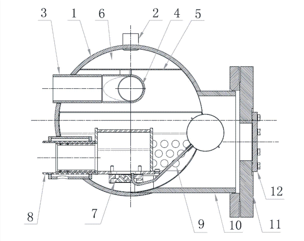
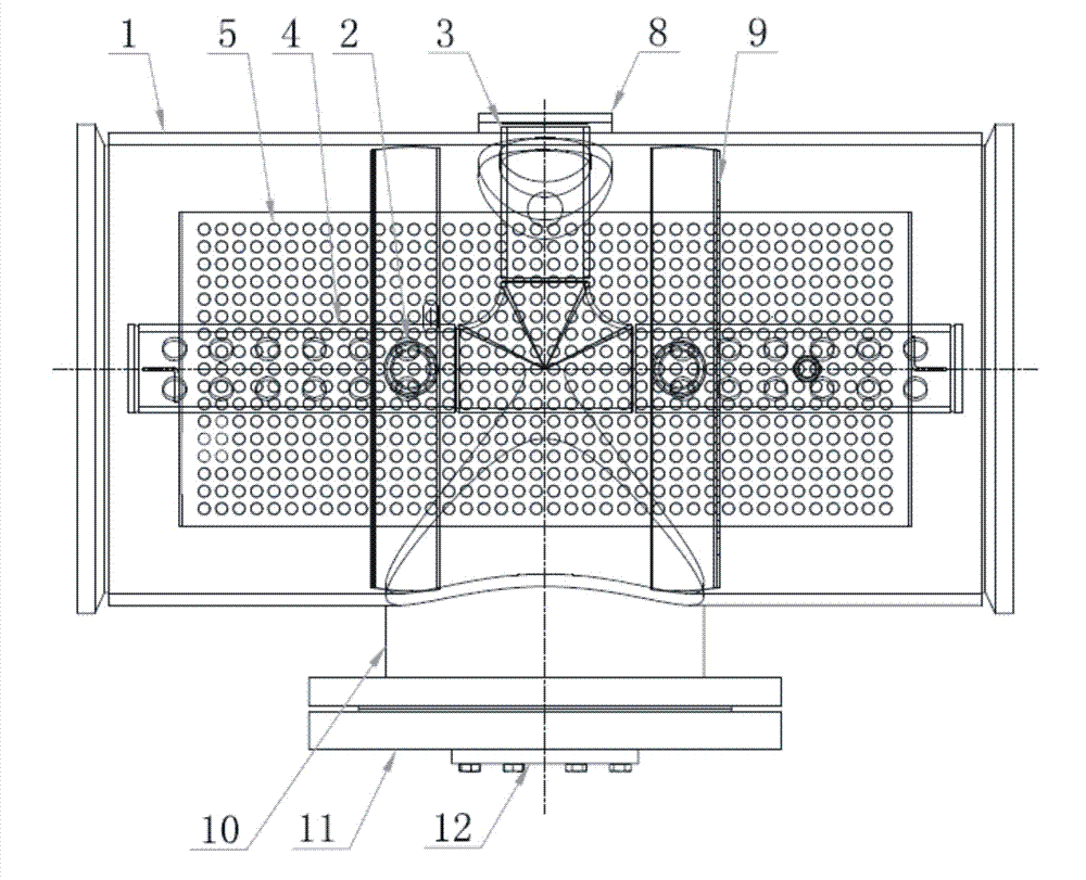
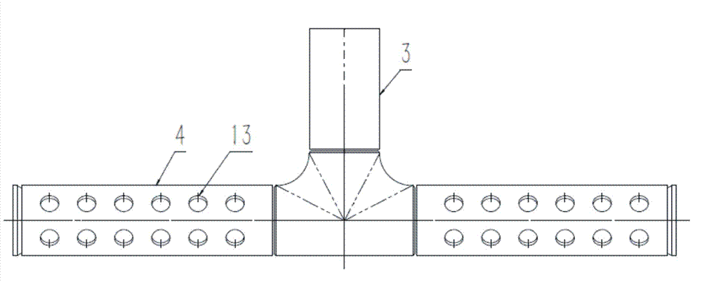
[0022] Such as figure 1 As shown, a flash type economizer includes a cylinder body 1, flat plates are provided at both ends of the cylinder body 1, an air outlet 2 is provided at the top of the cylinder body 1, and an inlet port is provided on the upper side of the cylinder body 1. The liquid pipe 3, the liquid inlet pipe 3 is separated into a double-sided liquid spray pipe 4 after being passed through a tee, and an air equalizing plate 5 is arranged above the inside of the cylinder body 1, and both sides of the air equalizing plate 5 are welded to the cylinder body. The two ends of the gas plate 5 are provided with gas baffles 6 respectively. Below the gas equalizing plate 5 is a ball float valve assembly 7. The ball float valve assembly 7 is installed...


PUM


Abstract

The invention discloses a flash evaporation type economizer and a distributing method by adopting the flash evaporation type economizer. The flash evaporation type economizer comprises a barrel, wherein a liquid inlet pipe is arranged on one side above the barrel; the liquid inlet pipe is divided into two lateral liquid spraying pipes after tee joint flow dividing; an air-equalizing plate is arranged above the liquid spraying pipes; air-stopping plates are arranged at the two ends of the air-equalizing plate; a float valve component is arranged under the air-equalizing plate; the float valve component is mounted in a liquid outlet sleeve; the liquid outlet sleeve is welded on the barrel; buffer plates with openings in lower sides are arranged on the two sides of the float valve component; a floater chamber is welded on one side, opposite to the liquid outlet sleeve, of the barrel; a flange is used for sealing the floater chamber; a liquid-viewing mirror is arranged on the flange. When the flash evaporation type economizer runs, the liquid level is stable and the reliability is high; when the running condition is changed, the adjustment is quick and high-efficient; a sleeve type mounting mode is adopted, so that the detaching and maintaining are easy; the whole cost is low.

Description

technical field [0001] The invention relates to the technical field of air-conditioning equipment, in particular to a flash economizer and a cloth distribution method using the same. Background technique [0002] The economizers used in high-efficiency cold water (heat pump) units in the refrigeration and air-conditioning industry mainly include two types of evaporators: plate-exchange economizers and flash-type economizers. Among them, compared with plate-exchange economizers, flash-type economizers have With the advantages of small heat transfer temperature difference and high system efficiency, the application prospect of flash economizer is more extensive. According to the different liquid level control methods of the economizer, the flash economizer can be divided into a float valve type and an electronic expansion valve type. Among them, the float type means that the liquid level in the economizer is controlled by the float valve, that is, the float moves with the cha...

Claims


Application Information

Patent Timeline
IPC IPC(8): F25B39/02F25B41/04F25B43/00F25B41/00F25B41/20
CPCF25B39/02F25B43/00F25B2339/02F25B41/315F25B41/20
Inventor 徐峰邓乔林吴晶晶刘顺
Owner MCQUAY AIR CONDITIONING & REFRIGERATION WUHAN
Why Eureka
Try Eureka