Crankshaft dynamic balance testing and calibration method

A calibration method and crankshaft technology, applied in the static/dynamic balance test, measuring device, machine/structural component test, etc., can solve the problems of crankshaft bump damage, troublesome operation, inability to use dynamic balance detection, etc., to avoid bumping The effect of injury, easy operation and reasonable structure

Active Publication Date: 2015-04-08
TIANRUN IND TECH CO LTD
View PDF8 Cites 10 Cited by
  • Summary
  • Abstract
  • Description
  • Claims
  • Application Information

AI Technical Summary

Problems solved by technology

For a V-shaped crankshaft, since each crank pin is not on the same plane, each crank pin has a certain phase difference. During the dynamic balance test, each crank pin will have an unbalance of equal size and different direction, and the conventional method canno

Method used


Image

  • Crankshaft dynamic balance testing and calibration method
  • Crankshaft dynamic balance testing and calibration method
  • Crankshaft dynamic balance testing and calibration method

Examples


Embodiment Construction

[0016] Taking the three-cylinder V6 crankshaft as an example, the crankshaft dynamic balance detection and calibration method is described in detail. The specific implementation steps are as follows:

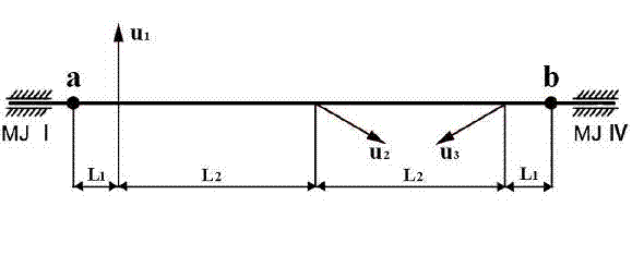
[0017] The first step is to carry out the unbalance conversion calculation first, decompose the unbalance on the three crank pins of the V6 crankshaft to the main journals at both ends, and calculate the unbalance of the crankshaft on the main journals at both ends. The unbalance quantity includes two physical quantities of unbalance mass and angle. The unbalanced angle is the included angle formed by the unbalanced direction on the circumference of the crankshaft and the line connecting the center of the first crank pin and the center of the main journal.

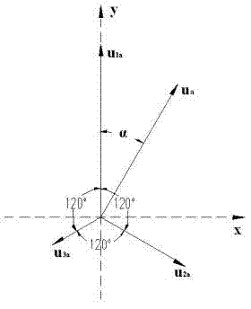
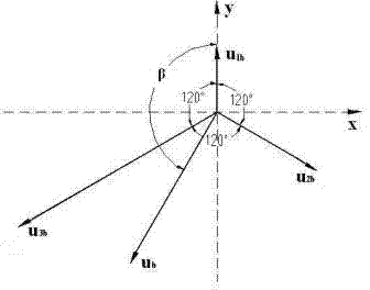
[0018] figure 1 It is a schematic diagram of distribution of crank pin unbalance in the present invention. figure 2 It is a combined schematic diagram of unbalanced quantities on plane a of the present invention. image ...


PUM


Abstract

The invention relates to a crankshaft dynamic balance testing and calibration method, which comprises the following steps of firstly, equivalently converting amount of unbalance of a crankshaft pin of a crankshaft to amount of unbalance, at some angle, on main journals at two ends of the crankshaft; secondly, manufacturing equivalent mass blocks according to the dimension of the crankshaft, installing the equivalent mass blocks on the main journals at two ends of the crankshaft, compensating self-unbalance of the crankshaft, and realizing basic dynamic balance of crankshaft mass; finally, carrying out crankshaft dynamic balance testing and calibration on a balance machine. According to the crankshaft dynamic balance testing and calibration method, the equivalent mass blocks are installed on the main journals at two ends and are reasonable in structure, and convenient and reliable to install. The crankshaft dynamic balance testing and calibration method can effectively avoid collision caused when an equivalent ring is installed on the crankshaft pin, is high in use safety, simple and convenient to operate, accurate to control and high in detection efficiency, and is an ideal crankshaft dynamic balance testing and calibration method.

Description

technical field [0001] The invention relates to a crankshaft dynamic balance detection technology, in particular to a crankshaft dynamic balance detection and calibration method. Background technique [0002] After the crankshaft of the automobile engine is processed, a dynamic balance test is required to ensure the rotation balance of the crankshaft in the engine. For a V-shaped crankshaft, since each crank pin is not on the same plane, each crank pin has a certain phase difference. During the dynamic balance test, each crank pin will have an unbalance of equal size and different direction, and the conventional method cannot be used for dynamic balance testing. . In the past, the traditional dynamic balancing scheme of this type of crankshaft used to add an equivalent ring to the crank pin, but this operation was very troublesome and easily caused the crankshaft to be bumped and damaged. Contents of the invention [0003] The technical problem to be solved by the presen...

Claims


Application Information

Patent Timeline
IPC IPC(8): G01M1/38
Inventor 丛建臣孙军倪培相慈惟红于东伟
Owner TIANRUN IND TECH CO LTD
Why Eureka
Try Eureka