Device for eliminating and monitoring PT (Potential Transformer) secondary circuit voltage drop

A monitoring device and secondary circuit technology, applied in the field of power systems, can solve problems such as inconvenient operation and management of the device, achieve the effects of saving maintenance costs, realizing real-time monitoring, and convenient maintenance and replacement

Inactive Publication Date: 2015-04-08
ELECTRIC POWER SCI RES INST OF GUIZHOU POWER GRID CO LTD +2
View PDF9 Cites 5 Cited by
  • Summary
  • Abstract
  • Description
  • Claims
  • Application Information

AI Technical Summary

Problems solved by technology

[0005] (3) Most of the existing devices lack the function of monitoring the working conditions of the PT secondary circuit (voltage, current, power, power factor), and the operation and management of the device are inconvenient

Method used


Image

  • Device for eliminating and monitoring PT (Potential Transformer) secondary circuit voltage drop
  • Device for eliminating and monitoring PT (Potential Transformer) secondary circuit voltage drop

Examples


Embodiment 1

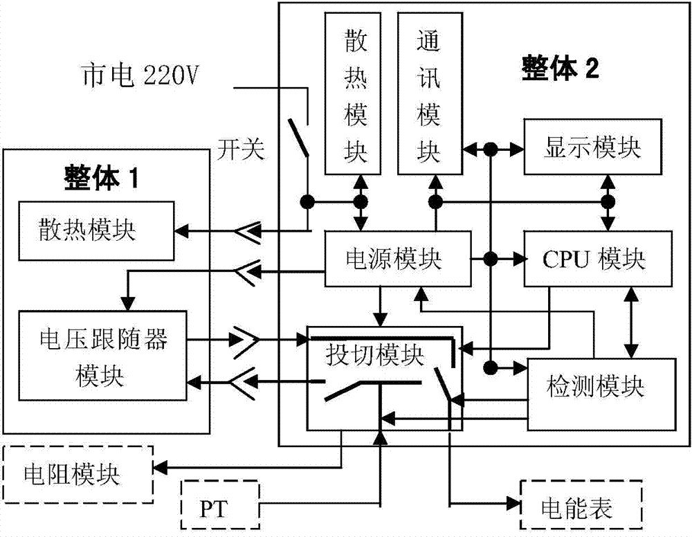
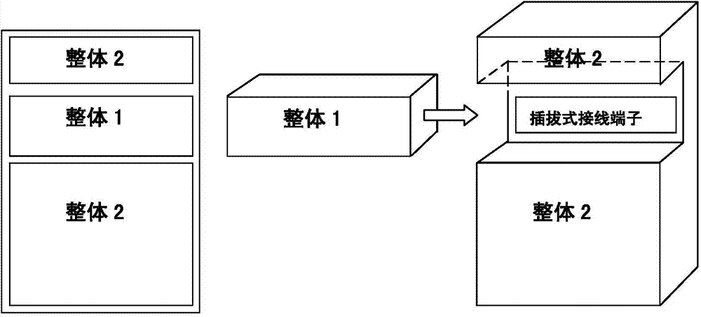
[0027] Such as figure 1 As shown, in this embodiment, the voltage follower module circuit and the follower cooling module circuit are formed into an independent whole 1, that is, the first unit, and other modules of the device such as a power module, a detection module, a CPU module, a communication module, a display module, and a switching module The circuit forms an independent whole 2, that is, the second unit, and the whole 1 circuit is separated from the whole 2 circuit, and is connected in a plug-and-pull manner through conductive terminals. The outer surface of the whole 1 is provided with 16 terminal conductive contacts, and the said whole 2 is provided with 16 terminal conductive contacts paired with it; among them, 8 terminal contacts are used for the electrical connection of the voltage follower module circuit and the switching module , 6 terminal contacts are used for the electrical connection of the voltage follower module circuit and the power module. The whole ...

Embodiment 2

[0035] This embodiment says the mode of concrete engineering application:

[0036] 1. Independent whole 1

[0037] 1. The voltage follower circuit module and heat dissipation module constitute an independent whole1.

[0038] 2. The independent whole 1 is connected with the independent whole 2 by plugging and unplugging

[0039] 3. The working power of the independent whole 1 is provided by the independent whole 2

[0040] Two, independent whole 2

[0041] 1. The working power module, CPU module, switching module, detection module, heat dissipation module and communication module constitute an independent whole2

[0042] 2. The independent whole 2 is connected to the PT secondary circuit in series near the end of the electric energy meter

[0043] 3. Independent overall 2 output signal control in the PT outlet terminal box and connected in parallel to the resistance module of the PT secondary circuit and the voltage follower to switch synchronously

[0044] 3. Accessories ...


PUM


Abstract

The invention discloses a device for eliminating and monitoring PT (Potential Transformer) secondary circuit voltage drop. The device comprises a voltage follower module circuit, a power module, a detection module, a CPU (Central Processing Unit) module and a switching module circuit, wherein the detection module is used for carrying out real-time sampling detection on an input / output end of the voltage follower module circuit; the CPU module decides the switching between the voltage follower module and an external resistance module through sampling, comparing and analyzing received electric power data so as to monitor a working condition of the voltage follower module; a circuit of the voltage follower module is packaged to form a first unit; circuits of the power module, the detection module, the CPU module and the switching module are packaged to form a second unit; the first unit and the second unit are movably connected through a pluggable connecting terminal; conductive contacts are arranged on the outer surface of the first unit, and paired conductive contacts are arranged on the second unit; part of the contacts are used for electrically connecting the voltage follower module circuit and the switching module, and the other part of the contacts are used for electrically connecting the voltage follower module circuit and the power module.

Description

technical field [0001] The invention relates to the field of power systems, in particular to a PT secondary circuit voltage drop elimination and monitoring device in the power industry based on the principle of a voltage follower. Background technique [0002] DL / T448-2000 "Management Regulations for Electric Energy Metering Management Technology" stipulates the allowable range of voltage drop in the PT secondary circuit of various electric energy metering devices. The domestically produced PT secondary circuit voltage drop elimination devices based on the voltage follower principle all adopt an integrated product structure, and there are the following problems in actual work: [0003] (1) Follower circuit components need to be replaced and repaired in time when the circuit components are damaged or cannot meet the working performance requirements due to self-heating, inadequate ventilation and heat dissipation, sudden changes in external voltage, inrush current, etc. The de...

Claims


Application Information

Patent Timeline
Patent Type & Authority Applications(China)
IPC IPC(8): G01R35/02G01R15/00
Inventor 李鹏程肖永王玉萍杨沁晖许爱丰钱坤
Owner ELECTRIC POWER SCI RES INST OF GUIZHOU POWER GRID CO LTD
Why Eureka
Try Eureka