Touch module

A technology of touch module and touch area, applied in the direction of instrument, electrical digital data processing, input/output process of data processing, etc., can solve the problems of high wire resistance and affecting signal transmission effect, etc., to improve conductivity, The effect of reducing process cost and reducing impedance

Inactive Publication Date: 2015-04-08
INTERFACE OPTOELECTRONICS SHENZHEN +1
View PDF4 Cites 8 Cited by
  • Summary
  • Abstract
  • Description
  • Claims
  • Application Information

AI Technical Summary

Problems solved by technology

However, if ITO is used as the wire in the routing area, its wire res

Method used


Image

  • Touch module
  • Touch module
  • Touch module

Examples


Embodiment Construction

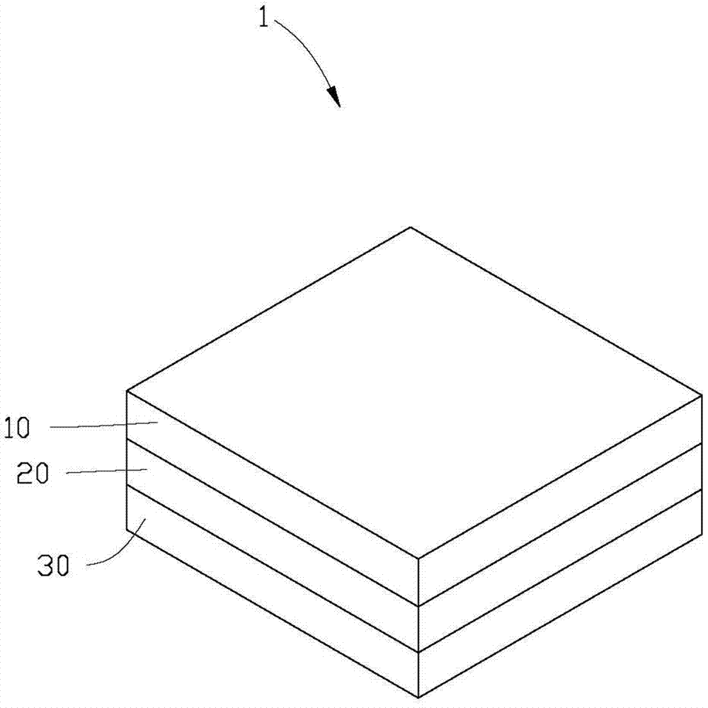
[0026] see figure 1 , figure 1 It is a three-dimensional schematic diagram of the touch display device 1 provided by the present invention. The touch display device 1 includes a cover glass 10 , a touch module 20 and a display module 30 stacked on top of each other. The cover glass 10 is also called cover lens or cover glass. The touch module 20 is sandwiched between the cover glass 10 and the display module 30 . Preferably, in one embodiment, the touch module 20 can be glued together with the glass cover 10 and the display module 30 by optical glue. For example, the optical adhesive may be an adhesive with high light transmittance such as optical clear adhesive (Optical Clear Adhesive, OCA) or optical clear resin (Optical Clear Resin, OCR).

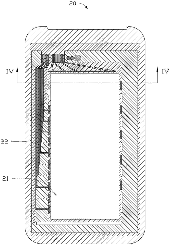
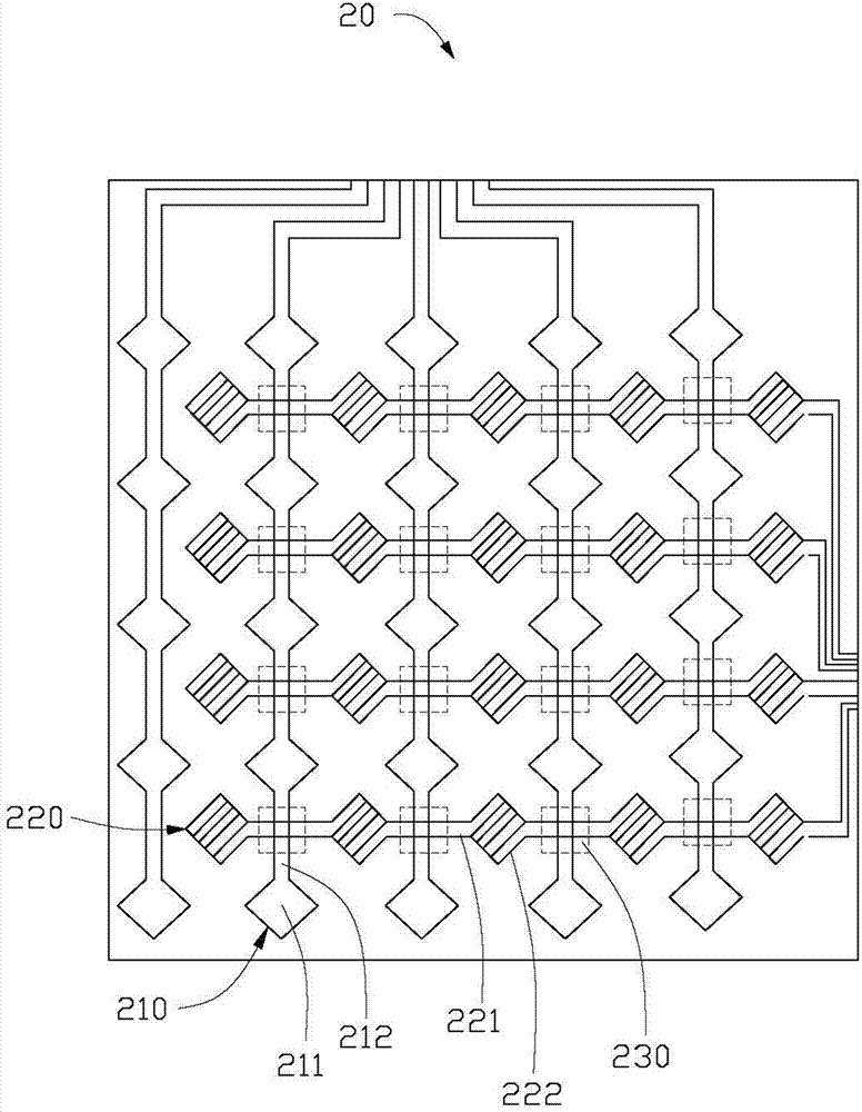
[0027] see figure 2 , figure 2 yes figure 1 A schematic diagram of the wiring structure of the touch module 20 shown in . The touch module 20 includes a touch area 21 and a wiring area 22 located around the touch area 21 . The...


PUM


Abstract

A touch module comprises a touch area, a routing area and a substrate, wherein the routing area is positioned on the periphery of the touch area; a first sensing electrode and a second sensing electrode which are made of conductive materials are arranged on the substrate and correspond to the touch area; the first sensing electrode is insulated from the second sensing electrode; and a conductive signal wire is arranged on the substrate, corresponds to the routing area and comprises at least two layers of conductive structures comprising a first conductive layer and a second conductive layer which are stacked.

Description

technical field [0001] The invention relates to a touch module. Background technique [0002] With the continuous development of electronic technology, most consumer electronic products such as mobile phones, portable computers, personal digital assistants (PDAs), tablet computers, and media players use touch modules as input devices to make the products more user-friendly. machine interaction. [0003] According to different touch principles, touch modules include resistive touch modules, capacitive touch modules, infrared touch modules, and acoustic wave touch modules. Currently, widely used touch modules include resistive, capacitive, optical, and acoustic touch modules. Among them, capacitive touch modules are more widely used. Capacitive touch modules are widely used in various consumer electronics products due to their good touch sensitivity, long service life, and less interference from external signals. [0004] At present, capacitive touch modules widely used, s...

Claims


Application Information

Patent Timeline
IPC IPC(8): G06F3/044
CPCG06F3/044
Inventor 戴嘉骏
Owner INTERFACE OPTOELECTRONICS SHENZHEN
Why Eureka
Try Eureka