Adjustable antenna for all-metal structural communication terminal equipment

A communication terminal, all-metal technology, used in antennas, slot antennas, antenna supports/installation devices, etc., can solve problems such as inability to effectively radiate or receive electromagnetic wave signals, unsatisfactory working bandwidth, etc. Easy-to-adjust frequency bands for a wide variety of effects

Active Publication Date: 2015-04-08
SHANGHAI AMPHENOL AIRWAVE COMM ELECTRONICS CO LTD
View PDF7 Cites 14 Cited by
  • Summary
  • Abstract
  • Description
  • Claims
  • Application Information

AI Technical Summary

Problems solved by technology

[0005] The purpose of the present invention is to provide an adjustable antenna for all-metal structure communication terminal equipment to solve the problem that the existing antenna cannot effectively radiate or receive electromagnetic wave signals when it is applied to all-metal structure communication terminals
[0006] The second object of the present invention is to provide an adjustable antenna for all-metal structure communication terminal equipment to solve the problem of unsatisfactory working bandwidth when the existing antenna is applied to all-metal structure communication terminals

Method used


Image

  • Adjustable antenna for all-metal structural communication terminal equipment
  • Adjustable antenna for all-metal structural communication terminal equipment
  • Adjustable antenna for all-metal structural communication terminal equipment

Examples


Embodiment 1

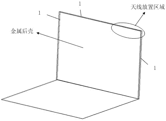
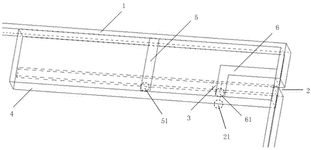
[0028] Such as figure 2 As shown, each side of the metal back shell is provided with a metal frame 1 , a gap 2 , an adjustable capacitor 3 and a bracket 4 . Wherein, the two ends of the adjustable capacitor 3 are respectively connected to the metal back shell at opposite sides of the gap 2, the first end of the gap 2 is located at the edge of the metal back shell, and has an open structure, and the second end of the gap 2 is located at the The shell of the metal back shell is a closed structure. The adjustable capacitor 3 is located near the second end of the slot 2 .

[0029] The bracket 4 covers the gap 2 and is adjacent to the metal frame 1 of the metal back shell. The bracket 4 is provided with a first metal sheet 5 and a second metal sheet 6. The first metal sheet 5 is a long strip structure, and one end It is electrically connected with the metal frame 1 , and the other end is used as the first grounding point 51 . The second metal sheet 6 has an L-shaped structure, a...

Embodiment 2

[0034] In this embodiment, other parts are the same as the first embodiment except that the adjustable capacitor is replaced by an inductor. Among them, in this embodiment, the adjustable capacitor is replaced by several parallel inductors, and each inductor is connected in series with a switch. When the antenna is working, the corresponding switch selects and connects different inductors, so as to realize the adjustment of the operating frequency of the antenna. Adjustment.

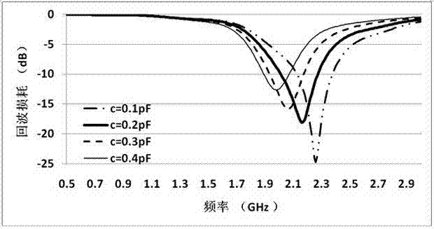
[0035] Such as Figure 4 As shown, only the test of the high frequency band is taken as an example to illustrate the influence of different inductance values ​​on the antenna. Figure 4 It is a graph of the return loss test results of the antenna when different inductances are connected in this embodiment. It can be seen from the figure that as the value of the loaded inductance increases, the resonant frequency of the antenna will move to the low frequency direction, thereby expanding the working band...


PUM


Abstract

The invention provides an adjustable antenna for all-metal structural communication terminal equipment. A slit is formed in a rear metal shell, and an adjustable electric device is connected between two sides of the slit. A bracket is arranged on the antenna; an annular antenna is formed by a metal sheet arranged on the bracket and a metal border on the rear metal shell; when the antenna is applied to the all-metal structural communication terminal equipment, an electromagnetic wave signal can be effectively radiated or received, and the high-frequency-band bandwidth of the antenna can be effectively expanded. By arrangement of the adjustable electric device, the working frequency band of the antenna can be adjusted, so that the bandwidth of the antenna is effectively expanded. The antenna is simple in structure; the working frequency band is easy to adjust, so that the adjustable antenna is very suitable for the all-metal structural communication terminal equipment.

Description

technical field [0001] The invention relates to an antenna, in particular to an adjustable antenna for communication terminal equipment with an all-metal structure. Background technique [0002] With the rapid development of wireless communication, its requirements on the rate and quality of data transmission are getting higher and higher. Currently, there are various technologies and standards for wireless communication. The development process of wireless communication from 2G to 3G and then to 3.9G is the process from mobile voice service to high-speed data service. Among them, LTE (Long Term Evolution, Long Term Evolution), as the main next-generation technology in the wireless network field, can provide faster transmission rate and higher transmission quality. In order to provide richer wireless communication functions, current mobile communication terminal devices such as notebook computers, tablet computers, and mobile phones need antennas that can meet various wire...

Claims


Application Information

Patent Timeline
Patent Type & Authority Applications(China)
IPC IPC(8): H01Q1/24H01Q23/00H01Q13/10
Inventor 胡沥盘龙
Owner SHANGHAI AMPHENOL AIRWAVE COMM ELECTRONICS CO LTD
Why Eureka
Try Eureka