Zero-crossing triggering circuit based on bidirectional silicon-controlled switch

A circuit and zero-crossing technology, applied in reactive power compensation, reactive power adjustment/elimination/compensation, etc., can solve the problems of large space occupation, high installation cost, capacity reduction, etc. The effect of suppressing inrush current and harmonics

Inactive Publication Date: 2015-04-08
YULIN UNIV
View PDF7 Cites 6 Cited by
  • Summary
  • Abstract
  • Description
  • Claims
  • Application Information

AI Technical Summary

Problems solved by technology

In the current trigger circuit based on the triac capacitive (TSC) arc suppressing coil, the method of suppressing the inrush current and harmonics at the moment of capacitor switching through the series reactor, that is, at the moment of system switching capacitor tuning, through The series reactor increases the reactance rate to suppress the inrush current and the corresponding harmonics generated b...

Method used


Image

  • Zero-crossing triggering circuit based on bidirectional silicon-controlled switch
  • Zero-crossing triggering circuit based on bidirectional silicon-controlled switch

Examples


Embodiment Construction

[0026] The present invention will be described in further detail below in conjunction with the accompanying drawings.

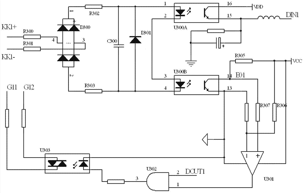
[0027] see figure 1 , the terminal signal description of the present invention: the positive input terminal KK1+, the negative input terminal KK1- are taken from the voltage signals of T1 and T2 at both ends of the bidirectional thyristor BTSC, and the bidirectional thyristor zero-crossing trigger drive signal passes through the first output terminal G11 , The second output terminal G12 is sent to the trigger signal terminals G1 and G2 of the bidirectional thyristor; DIN1 is the feedback signal of the working state of the bidirectional thyristor, which is directly sent to the I / O pin of the CPU of the device, and DOU1 comes from the switching of the CPU signal, trigger the conduction of the thyristor, and switch the capacitor device.

[0028] Description of the generation process of the signal of the present invention:

[0029] 1) Acquisition and rectificat...


PUM


Abstract

The invention discloses a zero-crossing triggering circuit based on a bidirectional silicon-controlled switch, including an input end for obtaining voltages signals of two ends of a silicon-controlled switch, and an output end for sending a zero-crossing triggering signal to the silicon-controlled switch, wherein a bridge type circuit for performing full-wave rectification on the voltages signals of two ends of the silicon-controlled switch, a first optocoupler for feeding the voltage signals back to a CPU (Central Processing Unit), a second optocoupler for performing level conversion on the voltages signals of two ends of the silicon-controlled switch to generate a corresponding preliminary zero-crossing pulse signal, a comparison amplifier for generating a silicon-controlled zero crossing point triggering signal, a gating element for performing AND on the zero crossing point triggering signal and a capacitor switch triggering signal sent by a process tuning CPU, and a driver for generating a silicon-controlled zero-crossing trigger driving signal are sequentially arranged between the input end and the output end. According to the zero-crossing triggering circuit, the silicon-controlled switch can be turned on by generating the triggering signals at the voltage zero crossing points of two ends of the bidirectional silicon-controlled switch; and the tuning transition process of a system can be stably completed by switching a capacitor in a system tuning process.

Description

technical field [0001] The invention relates to a reactive power compensation circuit of a power system, in particular to a zero-crossing trigger circuit based on a bidirectional thyristor. Background technique [0002] Due to the sudden change of the voltage across the capacitor, inrush current and a series of harmonics will be generated. In the current trigger circuit based on the triac capacitive (TSC) arc suppressing coil, the method of suppressing the inrush current and harmonics at the moment of capacitor switching through the series reactor, that is, at the moment of system switching capacitor tuning, through The series reactor increases the reactance rate to suppress the inrush current and the corresponding harmonics generated by the capacitor, so that the capacity of the arc suppressing coil to compensate the switching capacitor is correspondingly reduced. This compensation method has high device cost, large noise, and takes up a large volume space. At the same time...

Claims


Application Information

Patent Timeline
IPC IPC(8): H02J3/18
CPCY02E40/30H02J3/18
Inventor 王憨鹰李阳张秋艳冯宗君付佩琪王志军
Owner YULIN UNIV
Why Eureka
Try Eureka