
1*N multi-channel optical switch polling test system

A polling test, optical switch technology, applied in the direction of transmission monitoring/testing/fault measurement system, etc., can solve the problems of time-consuming and troublesome operation, and achieve the effect of saving time and easy operation.

Inactive Publication Date: 2015-04-08
武汉正光恒远科技有限公司
View PDF3 Cites 6 Cited by
  • Summary
  • Abstract
  • Description
  • Claims
  • Application Information

AI Technical Summary

Problems solved by technology

If you test a multi-port optical switch according to the conventional manual one-to-one port test method, you need to replace hundreds of test connection jumpers, and manually switch each channel in sequence, whether it is in the test preparation stage, during the test process or data. In the collection stage, the operation is extremely troublesome and time-consuming

Method used


Image

  • 1*N multi-channel optical switch polling test system
  • 1*N multi-channel optical switch polling test system

Examples


Embodiment Construction

[0023] In order to further explain the technical means and effects that the present invention takes to achieve the intended purpose of the invention, the specific implementation and work of the polling test system for the 1xN multi-channel optical switch proposed according to the present invention will be described below in conjunction with the accompanying drawings and preferred embodiments. The principle is explained in detail.

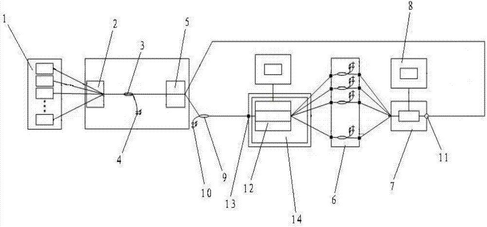
[0024] see figure 1, the polling test system for 1xN multi-channel optical switches provided by the embodiment of the present invention includes: a light source group 1, a first 1*N optical switch 2, a first 1*N coupler 3, a first Pin tube 4, a second 1*N optical switch 5, N channel power meter test module 6, third 1*N optical switch 7 and programmable controller 8; the output end of the light source group 1 is connected to the input end of the first 1*N optical switch 2, The output end of the first 1*N optical switch 2 is connected to the input en...


PUM


Abstract

The invention relates to the technical field of test systems, and discloses a 1*N multi-channel optical switch polling test system. The test system comprises a light source group, a first light switch, a coupler, a Pin tube, a second optical switch, N-channel power meter test module, a third optical switch and a programmable controller; the light source group is connected with the input end of the first optical switch; the output end of the first optical switch is connected with the input end of the coupler; the output end of the coupler is connected with the input end of the Pin tube; the output end of the Pin tube is connected with the programmable controller; the output end of the coupler is connected with the input end of the second optical switch; and output end of the second optical switch is connected with the input end of an optical switch to be tested; the output end of the second optical switch is connected with the input end of the third optical switch; the output end of the optical switch to be tested is connected with the input end of a test module; the output end of the test module is connected with the input end of the third optical switch; and the output end of the third optical switch is connected with the programmable controller. The 1*N multi-channel optical switch polling test system has the characteristics of convenience for operation and time saving.

Description

technical field [0001] The invention relates to the technical field of test systems, and is mainly applicable to polling test systems of 1xN multi-channel optical switches. Background technique [0002] With the expansion of the network, the increase of traffic types, the gradual development of FTTH (Fiber To The Home) technology and CATV (Community Antenna Television) technology, the previous 1x2 and 2x2 optical switches can no longer meet the requirements of the current 1x32, 1x64, and 1x128 optical links. multi-port requirements over the road. Due to too many ports, both the production of the optical switch and the test on the user side have the defects of cumbersome and time-consuming operations. Among them, the core indicators of optical switches include: insertion loss (IL), isolation (ISO), return loss (RL) and switching delay (switch time), and all of them need to be tested. [0003] The application scenario of the optical switch determines that the optical switch ...

Claims


Application Information

Patent Timeline
IPC IPC(8): H04B10/07
Inventor 张永红陈国祥
Owner 武汉正光恒远科技有限公司
Learn More